System integration in automated environments dictates specific power-to-weight ratios.
The objective in motion control is minimizing mechatronic volume while maximizing power output. This requires evaluating electromagnetic topologies, comparing radial and axial flux designs.
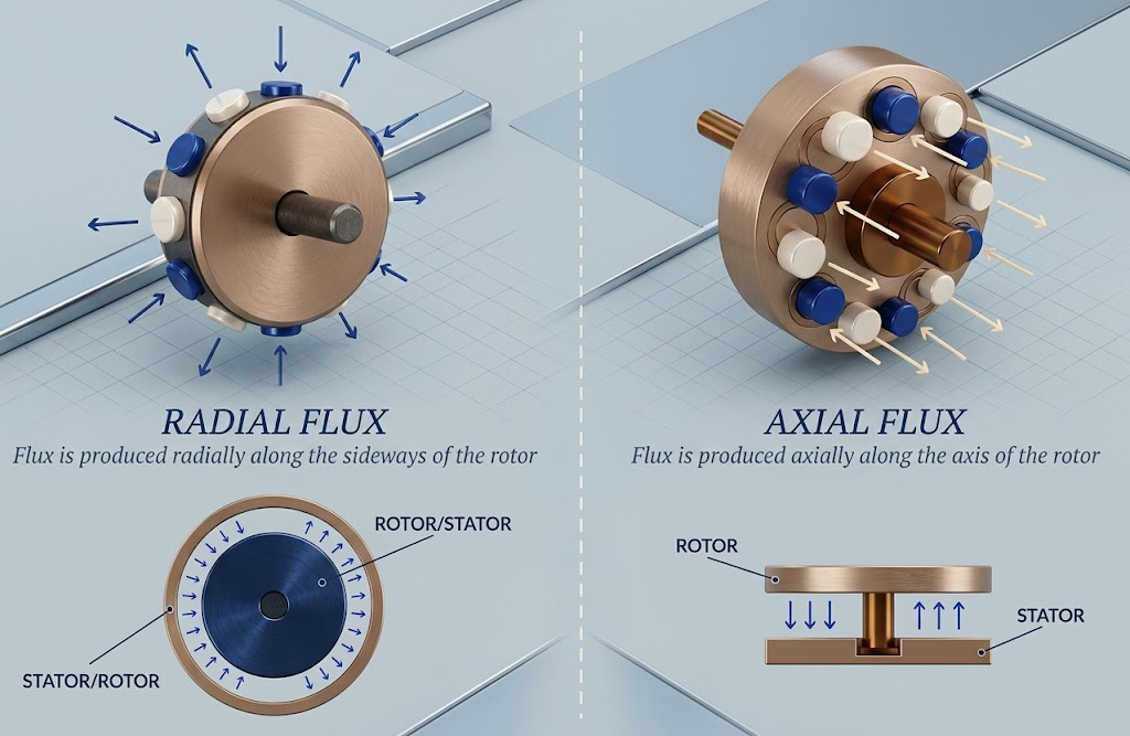
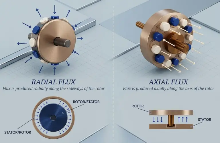
Figure 1: Comparison of electromagnetic flux trajectories between radial (perpendicular) and axial (parallel) topologies.
The Engineering Problem: Performance vs. Mass, Volume, and Thermal Dynamics
Robotic joints require high peak torque to absorb kinetic impacts (e.g., a bipedal robot step) while maintaining positional accuracy under load. As motor size decreases, the system’s capacity to dissipate heat drops. Operating high-power motors in confined spaces without adequate thermal management causes stator degradation and permanent demagnetization.
Optimizing torque density (torque output per unit of mass or volume) depends directly on the choice between radial and axial electromagnetic configurations.
Electromagnetic Topologies in Robotic Drives
Radial Flux Architecture
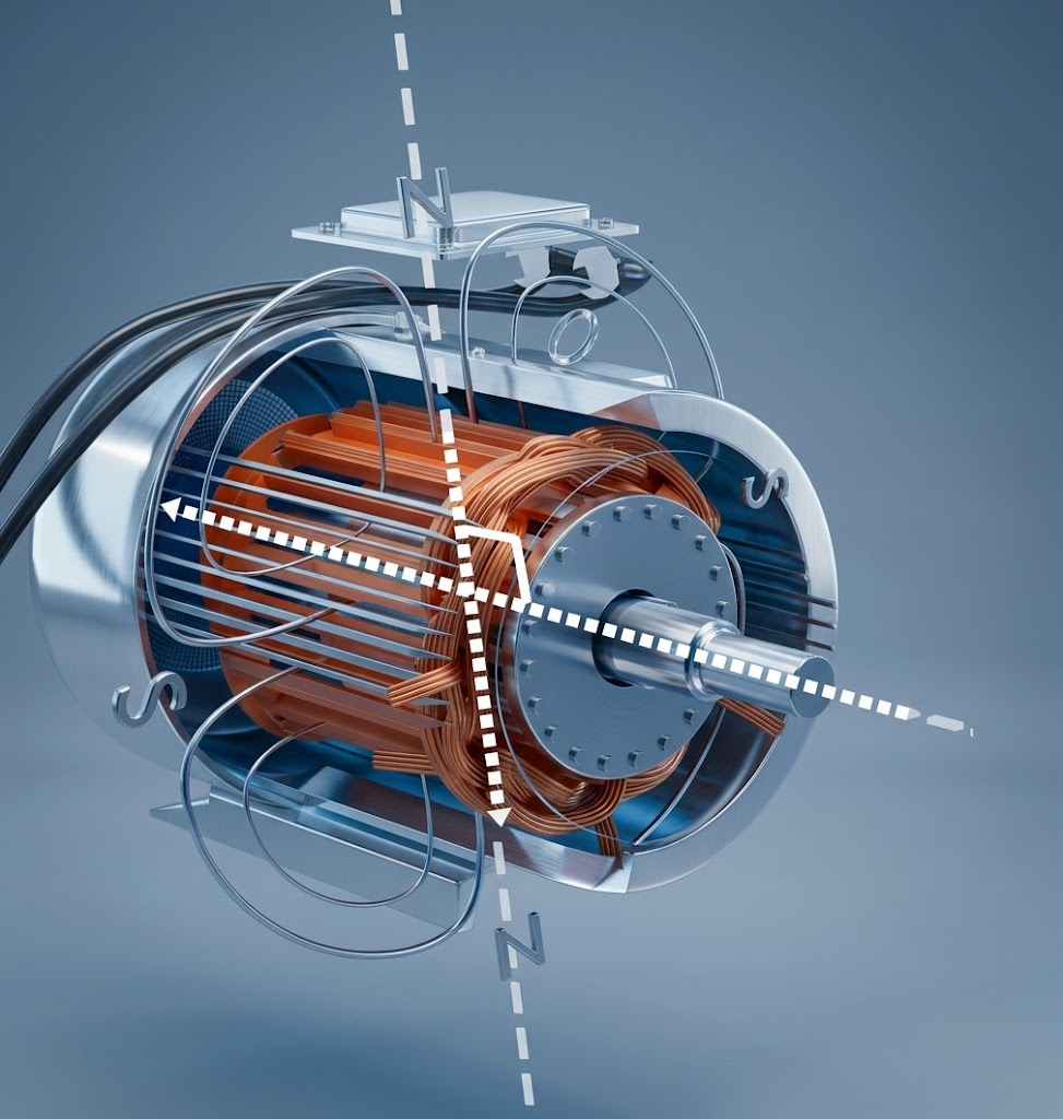
In a radial flux motor, the magnetic flux travels perpendicularly to the axis of rotation. The stator is arranged in a cylindrical format surrounding the internal rotor (or vice versa in outrunner configurations). This topology features standardized manufacturing processes and predictable thermal pathways via direct contact between the stator and the outer housing.
The primary geometric limitation of internal rotor (inrunner) radial motors is scalability. Increasing continuous torque generally requires increasing axial length. This elongated axial profile is a structural disadvantage in space-constrained applications. Recent variants, such as slotless radial motors, allow for diametric customization and address part of this issue.
Axial Flux Architecture
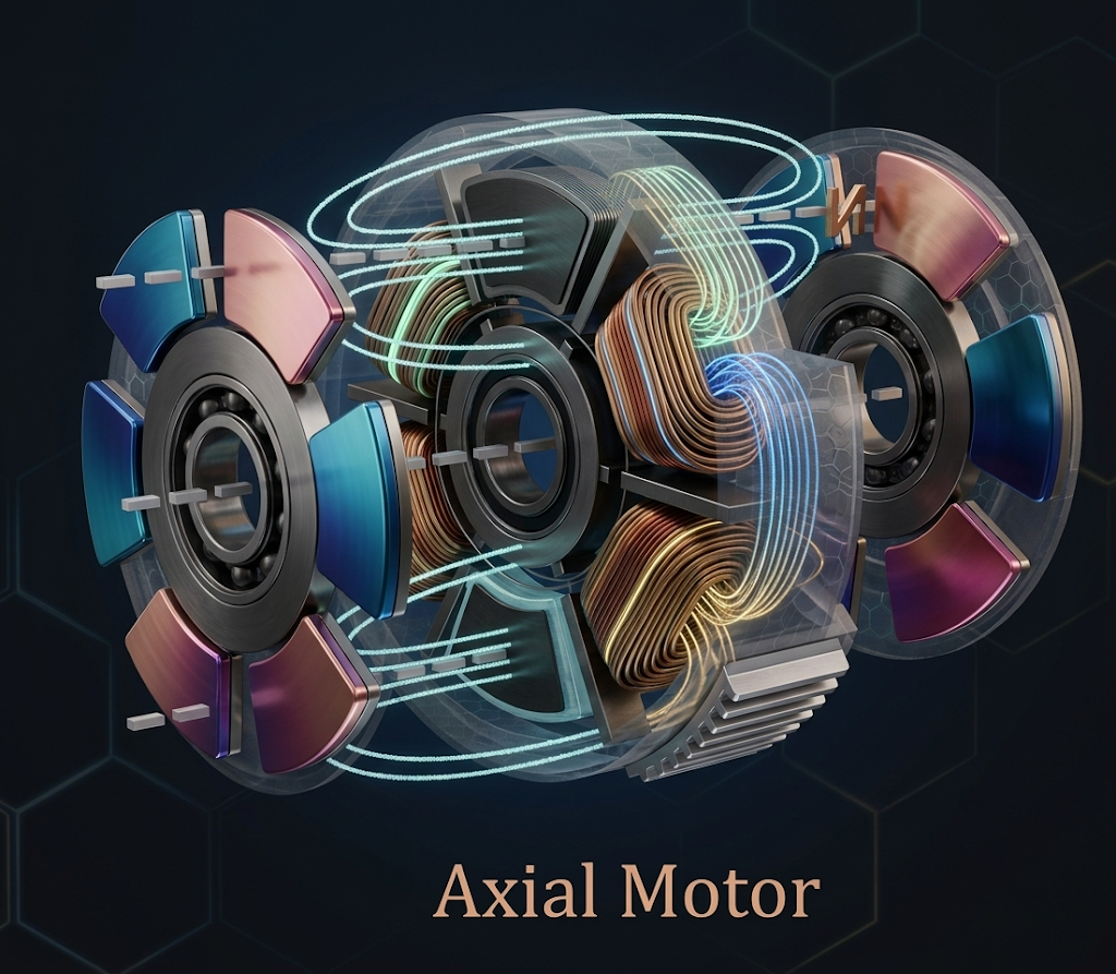
Axial flux motors operate with the magnetic flux traveling parallel to the axis of rotation. The rotor and stator are parallel discs, resulting in a planar profile.
Secure Your Components Stock Now with Torquety
Reliable automation components for high-performance applications.
This topology presents a shorter magnetic path, reducing core losses, and a larger effective air gap diameter, maximizing the magnetic force lever arm. This generates higher torque at lower speeds compared to a radial inrunner of equivalent volume. In high-performance applications, an axial configuration can achieve >30% volumetric and mass reduction versus a slotted radial motor of equivalent power, depending on the aspect-to-diameter ratio.
Figure 2: Internal cross-section of an axial flux motor (dual rotor / single stator topology).
Structural Integration in Advanced Robotics
Dynamic Platforms and Humanoids
Actuators must deliver peak power for dynamic movements while keeping weight low to avoid shifting the system’s center of gravity. Excess mass in extremities increases inertial load.
The compact format of axial flux motors enables coaxial integration with harmonic reducers in the same housing. However, utilizing hollow shafts for cable routing presents a technical trade-off: in axial flux motors, the central hole removes active electromagnetic area from the discs, penalizing torque density more severely than in radial topologies.
Direct Propulsion in AMRs
AMRs and AGVs require in-wheel direct propulsion to eliminate mechanical transmission losses. The planar profile of the axial flux motor fits inside the wheel hub, freeing chassis space for batteries or sensors.
Thermal Management
The typical dual-rotor, single-stator topology in axial flux motors presents thermal management challenges. The central stator, where copper losses generate heat, is flanked by rotating rotors, restricting passive thermal conduction paths to the exterior. Operating at high continuous duty cycles requires specific designs, such as segmented stators, ironless printed circuit board (PCB) windings, or active cooling encapsulation. Ironless (coreless) designs nearly eliminate iron losses, allowing operation at extremely high speeds without the overheating associated with steel-core stators.
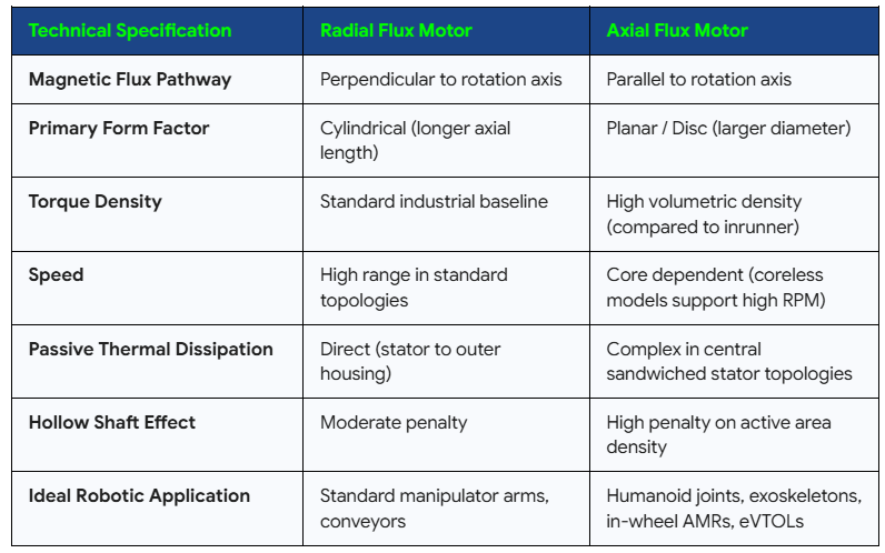
Technical Specification Comparison
Supply Chain Volatility
Assembly processes and strict air gap tolerances required for axial flux topologies result in extended production lead times. Procurement data indicates delivery times for specialized high-performance motors range between 18 and 24 months. Migration requires accounting for mounting tolerances, altered inertias, and firmware adjustments in the controller.
References
- International Federation of Robotics (IFR). (2024). Global Robot Density in Factories Doubled in Seven Years.
- Interact Analysis. (2026). Mobile robots market outpaces fixed automation with 19% annual growth to 2030.
- IndustryARC. (2024). Axial Flux Motor Market Size Report, 2024-2030.
- Credence Research. (2025). Axial Flux Motor Market Size, Share, Growth and Forecast 2032.
- Market Growth Reports. (2026). Axial Flux Motor Market Size, Share | Global Research [2034].
For further reading, we highly recommend checking out Hybrid Slip Ring Assemblies for Defense: Architecture and Transmission Requirements, as well as our articles on Servo Drive Grounding: Earth Ground, Chassis Ground, and Signal Ground Explained and Cable Shielding for Servo Encoder Systems: Grounding Practices and Ground Loop Mitigation.
Need a Custom Component Solution?
Contact our engineering team to discuss your application requirements and get a custom quote.