Integrating a through-bore slip ring into an electromechanical system solves the core operational challenge of routing secondary mechanical elements (such as hydraulic lines, pneumatic conduits, or a central drive shaft) directly through the center of unlimited, continuous 360° rotation.
However, mismatched mechanical tolerances, rigid dual-ended mounting, and improper tracking of electrical noise can cause premature contact wear and structural failure. Maintaining systemic concentricity and managing operational loads dictates strict compliance with defined mechanical installation guidelines and electrical parameters.
Mechanical Architecture and Core Specifications
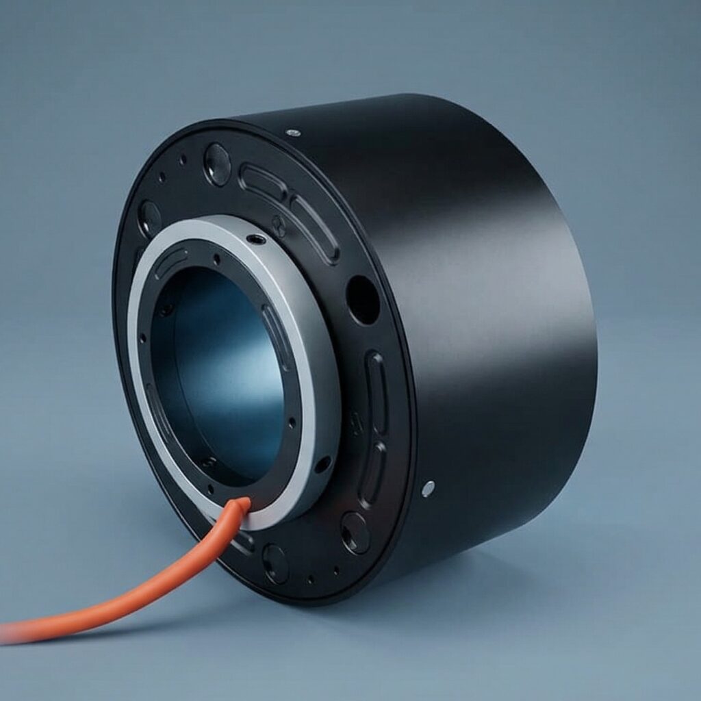
A through-bore slip ring utilizes an unobstructed central inner diameter (ID) designed for a slip fit over a mating drive shaft. The internal structure comprises a rotating core (rotor) containing the electrical rings, and a stationary brush carriage (stator) holding the brush blocks.
Technical parameters vary based on the frame size and contact technology utilized across standard product series:
Secure Your Components Stock Now with Torquety
Reliable automation components for high-performance applications.
- Bore Dimensions: Unobstructed internal diameters scale from 0.5 inches (12.7 mm) up to 9.0 inches (228.6 mm) to accommodate different shaft and media routing requirements.
- Rotational Velocities: Maximum operational speeds scale inversely with diameter. Small bore units (0.5 in to 3.0 in) support speeds up to 1,000 rpm, whereas larger installations (4.0 in to 9.0 in) are limited to a maximum of 600 rpm.
- Contact Passages: Configurations support up to 100 signal circuits (rated up to 250 V / 5 A each) or up to 24 power circuits (rated up to 600 V / 30 A each).
- Wiring Terminals: Standard configurations use color-coded flying lead wire bundles, typically utilizing 20 AWG flying leads for signal circuits and 12 AWG flying leads for power paths. High-impact thermoplastic or all-metal exterior covers protect the internal assembly.
Contact Technology and Electrical Performance
The reliability of transmission across a rotating gap depends on the galvanic interface. Modern through-bore slip rings utilize two primary contact methods: fiber brush technology and silver-composite block assemblies.
| Performance Metric | Fiber Brush Technology | Silver-Composite Assemblies |
| Primary Application | High-density data, Ethernet, low-current signals | High-current power distribution |
| Points of Contact | Multiple redundant points per brush bundle | Single solid block interface |
| Maintenance Profile | Lubrication-free; virtually zero wear debris | Field-replaceable with standard tools |
| Max Electrical Noise | 100 milliohms maximum | Variable based on additive formulations |
| Operating Temp Range | -40°C to +80°C | -20°C to +80°C |
Fiber brush bundles operate with extremely low contact force per fiber, minimizing the contact wear rate during continuous bidirectional rotation. For power configurations using silver-composite brushes, replacement brush blocks can be swapped out via standard socket wrenches. Custom silver-composite formulations with specific additives are applied when assemblies encounter severe operating environments or require extended brush lifetimes.
Isolation of Stress via Soft-Mounting Protocols
A critical engineering rule when designing the installation of a through-bore slip ring is the absolute avoidance of “hard mounting” (rigidly fixing) both the rotating and stationary sections simultaneously.
Because a slip ring is not designed to bear the structural weight of external equipment, any concentricity deviations or axial run-out in the rotating mechanical system will transfer directly into the slip ring bearings if both ends are locked. This induces severe radial side-loading, leading to rapid bearing degradation and erratic brush tracking.
To isolate the assembly from mechanical stresses, systems must employ a “soft-mounting” or floating arrangement:
- Rotor Coupling: The inner portion (ID) of the slip ring must be secured directly to the rotating drive shaft. This is achieved via a dedicated mounting collar kit that fastens to the slip ring rotor section and clamps to the shaft using two set-screws positioned approximately 100° apart. This adds exactly 0.50 inches to the overall unit length.
- Stator Isolation: The outer portion (OD) of the housing must remain free to float axially and radially. A drive adapter kit or anti-rotation torque arm must be fitted loosely over a stationary pin or dowel. This pin-in-slot arrangement prevents the stator from rotating while introducing the compliance needed to absorb system alignment variances.
- Lead Wire Routing: Flying leads must be secured so they do not contact surrounding machinery surfaces during rotation. Wires must be routed with sufficient slack to prevent the lead bundles from applying any secondary side-loading or axial tension to the slip ring exits.
Need a Custom Component Solution?
Contact our engineering team to discuss your application requirements and get a custom quote.