As manufacturing facilities transition to Industry 4.0 smart factory architectures, position encoders must do more than simply supply raw positional data. Modern digital protocols (such as BiSS-C, SSI, SPI, and high-speed UART) enable real-time diagnostic reporting, temperature monitoring, and error checking directly over high-speed differential communication lines. Autorotation, self-configuration, and predictive maintenance are no longer optional additions; they are core requirements enabled by smart position sensors.
💡 Lead Editor’s Engineering Insight
In high-performance motion control, the communication protocol is just as vital as the physical sensing technology. Integrating absolute position feedback with high-speed digital diagnostics allows modern motion controllers to detect faults dynamically, compensate for cable delays automatically, and scale complex multi-axis systems without additional wiring.
Key Technical Considerations & Operational Characteristics
When integrating feedback sensors into motion control systems, design engineers must balance positional resolution against real-world mechanical tolerances and environmental vulnerabilities. Traditional optical glass discs require precise axial alignment and sealed housings to prevent failure from dust or liquid ingress. Conversely, magnetic encoders provide environmental ruggedness but can suffer from non-linearities and hysteresis.
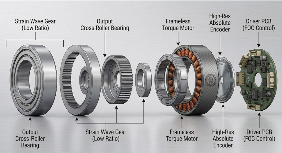
To meet the demands of Industry 4.0, next-generation systems utilize bearingless, frameless absolute encoders. By scanning a full 360° scale, these encoders eliminate mounting-induced errors and run completely hysteresis-free. This real-time, jitter-free performance is crucial for smooth velocity control and high-precision positioning.

Secure Your Components Stock Now with Torquety
Reliable automation components for high-performance applications.
“FLUX encoder technology bridges the gap between optical-grade precision and magnetic-grade robustness, delivering uncompromised absolute feedback in the most challenging industrial environments.”
Deep Dive: Industry-Standard Digital Encoder Protocols
Modern absolute encoders utilize serialized digital protocols rather than legacy analog resolver signals or incremental A/B/Z pulses. Below, we break down the key characteristics and implementation configurations of the industry’s dominant interfaces:
1. BiSS-C (Bidirectional Synchronous Serial)
BiSS-C is an open-source, high-speed, bidirectional communication protocol designed for industrial sensors. It operates in a continuous mode, sending position updates on every clock cycle with minimal latency.
- Bidirectional Register Access: Allows the motion controller to read and write directly to specific registers within the encoder’s memory. This permits on-the-fly configuration, access to internal calibration factors, temperature monitoring, and electronic datasheet (EDS) retrieval.
- Line Delay Compensation: The master controller dynamically measures and compensates for propagation delays along long cable runs. This enables reliable data transfer at clock frequencies up to 5.0 MHz (and up to 10 MHz under optimized configurations).
- Advanced Diagnostics: Every data packet contains dedicated nE (Not Error, active low) and nW (Not Warning, active low) status flags, alongside a 6-bit Cyclic Redundancy Check (CRC) polynomial (0x43: \(X^6 + X^1 + X^0\)) to guarantee transmission integrity.
- FLUX Configurations:
- BIS00: A 40-bit frame reserving 32 bits for right-aligned position data. Highly suitable for linear scale applications.
- BIS10: A 32-bit frame reserving 24 bits for left-aligned position data. The standard choice for rotary systems with resolutions up to 24 bits.
- BIS20: A 40-bit frame reserving 32 bits for left-aligned position data, recommended for ultra-high resolution encoders (25-bit and higher).
- BIS21: An absolute multi-turn protocol reserving 32 bits of position data split between m Multi-Turn bits (up to 12 bits) and 32-m Single-Turn bits. Perfect for virtual multi-turn encoder setups.
2. SSI (Synchronous Serial Interface)
SSI is a highly reliable, point-to-point, unidirectional synchronous interface. It uses a shared clock signal supplied by the master controller and RS-485 differential line drivers to transmit absolute position data. Unlike BiSS-C, it is simpler but lacks native line compensation and register access.
To overcome these standard limitations, FLUX offers a versatile matrix of specialized SSI configurations:
- SSI00 (Absolute with Diagnostics): A 28-bit frame containing 25 right-aligned position bits and 3 status bits: E (Error, active high), W (Warning, active high), and P (Even Parity bit). Operating clock: 0.2 to 1.0 MHz.
- SSI01 (Position Only): Transmits only N position bits with no status overhead, allowing clock frequencies up to 2.0 MHz.
- SSI03 (Virtual Multi-Turn): A 46-bit frame transmitting up to 12 Multi-Turn bits, 32 Single-Turn bits, and 2 status bits (ME: Multi-Turn Error, SE: Single-Turn Error).
- SSI04: A 24-bit frame containing 22 right-aligned data bits and 1 active-low error flag (nE).
- SSI11 (Monoflop Error Transmission): Position-only N-bit stream that embeds error diagnostics in the monoflop time. If an error is detected, the data line is held at ‘1’ throughout the monoflop delay period.
- SSI20 (Dual Output Referenced/Non-Referenced): A unique 48-bit interface that outputs two position values: a 23-bit signed Position Referenced value (relative to a crossed reference mark), a 1-bit Referenced Flag, a 23-bit signed Position Not-Referenced value (continuous counting from power-on), and a status error bit.
3. SPI Compatibility via SSI
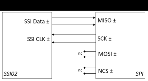
For space-constrained applications or low-cost microcontroller integrations where dedicated encoder transceiver ICs are not practical, FLUX offers the SSI02 interface. This interface is structured to be fully compatible with standard Serial Peripheral Interface (SPI) controllers.
By setting the motion controller to SPI Mode #2 (Clock Polarity CPOL = ‘1’ or Idle High, Clock Phase CPHA = ‘0’ or sample on falling edge), the encoder behaves as an SPI slave.
Only two lines are connected: SSI Data to Master In Slave Out (MISO) and SSI Clock to Serial Clock (SCK). The Slave Select (NCS) and MOSI lines remain unconnected, leaving the encoder continuously enabled.
The 24-bit frame delivers a reserved MSB (always ‘1’), a high-reliability Error bit (where ‘0’ indicates a valid position and ‘1’ indicates an encoder fault), and 22 bits of right-aligned absolute position data.
4. UART (Asynchronous Serial)
When synchronous clock lines are undesirable due to electromagnetic emissions or wiring limits, the FLUX UATxx Universal Asynchronous Transmitter interface provides a highly robust alternative. Utilizing RS-485/RS-422 differential physical layers, the UATxx transmits data continuously over a single TX± line pair. Position data is packed into 6-byte frames featuring a 16-bit CRC (0x8005 polynomial) and an NER (No Error Bit) flag.
Engineers can select between two preset speeds: UAT00 (230,400 bps baud rate with a 2.5 kHz frame update cycle) or the high-speed UAT01 (921,600 bps baud rate with a 10 kHz frame update cycle) to match the dynamic demands of the loop.
5. High-Speed Quadrature (A/B/Z Incremental)
For legacy controllers and high-velocity applications, FLUX’s INCxx Quadrature output generates differential square-wave A and B signals with a 90° phase shift, alongside a Z index pulse for homing. Configurations scale from INC03 (0.625 MHz cycle frequency) up to the blistering INC00 (5.0 MHz cycle frequency), which translates to a massive 20.0 million counts per second after standard x4 decoding.
How Patented GMI® and Inductive Sensors Leverage Digital Protocols
FLUX position encoders combine advanced digital protocols with physical sensing architectures that are optimized for smart motion control:
- GMI® (Giant Magneto Impedance) Technology:
FLUX’s patented GMI® technology utilizes the skin effect to measure position by tracking impedance changes in soft magnetic materials. GMI® encoders deliver the accuracy of optical glass encoders (rotational accuracy of ±4 arcseconds for GMI-ANG, and up to 24-bit resolution) with the mechanical robustness of magnetic sensors. These high-accuracy rings are typically paired with high-bandwidth BIS10/BIS20/BIS21 BiSS-C protocols to maintain real-time position updates without calibration. - Inductive Technology:
FLUX’s patent-pending inductive absolute encoders are designed for narrow spaces, offering the thinnest frameless designs on the market. The open PCB IND-ROT series is less than 6mm thick and weighs just 14g. Because it is completely immune to stray magnetic and electromagnetic fields, it can be integrated directly inside electric motors. Paired with compact SSI00-SSI04 or BIS00 protocols, they provide up to 25-bit absolute resolution directly inside frameless motor housings. - IND-MAX Heavy-Duty Series:
For extreme land, sea, or aerospace applications, the IND-MAX encapsulated IP67 series operates in temperatures from -40°C to +85°C (extended range up to +125°C). Utilizing SSI or BiSS-C, IND-MAX sensors transmit real-time diagnostics to alert the controller of any environmental threat or signal degradation before a system shutdown occurs.
Encoder Protocol Configuration & Capability Matrix
| FLUX Protocol | Physical Layer | Position Type | Line Delay Comp. | Register Access | Diagnostics & Checksums | Max Clock / Speed |
|---|---|---|---|---|---|---|
| BIS00 | BiSS-C (RS-485) | Absolute (Linear) | Yes | Yes | 6-bit CRC + nE/nW flags | 5.0 MHz (up to 10 MHz) |
| BIS10 | BiSS-C (RS-485) | Absolute (Rotary ≤24-bit) | Yes | Yes | 6-bit CRC + nE/nW flags | 5.0 MHz (up to 10 MHz) |
| BIS20 / 21 | BiSS-C (RS-485) | Absolute (Rotary ≥25-bit / MT) | Yes | Yes | 6-bit CRC + nE/nW flags | 5.0 MHz (up to 10 MHz) |
| SSI00 | SSI (RS-485) | Absolute (25-bit position) | No | No | Error (E), Warning (W), Parity (P) | 1.0 MHz Clock |
| SSI02 | SPI Compatible | Absolute (22-bit position) | No | No | Error (E) bit | 1.0 MHz Clock (SPI Mode 2) |
| SSI03 | SSI (RS-485) | Absolute (Multi-Turn) | No | No | Multi (ME) & Single (SE) Errors | 2.0 MHz Clock |
| UAT01 | UART (RS-485) | Absolute (24-bit position) | No | No | 16-bit CRC (0x8005) + NER flag | 921,600 bps (10 kHz cycle) |
| INC00 | Quadrature A/B/Z | Incremental | No | No | Differential physical verification | 5.0 MHz (20M counts/sec) |
Selecting the Right Encoder for Your Application
Selecting the appropriate protocol and configuration is just as critical as selecting the physical encoder geometry. While standard robotic arm joints benefit from the multi-turn diagnostics of BiSS-C BIS21, direct-drive brushless motors can utilize the high-speed noise immunity of UART UAT01 or the simplicity of SPI-compatible SSI02.
Whether designing a next-generation surgical robot arm, a high-torque frameless motor drive, or a marine subsea actuator, the FLUX Smart Communication Digital Series provides the mechanical flexibility, environmental protection, and electrical reliability required for state-of-the-art closed-loop motion control.
Need a Custom Component Solution?
Contact our engineering team to discuss your application requirements and get a custom quote.