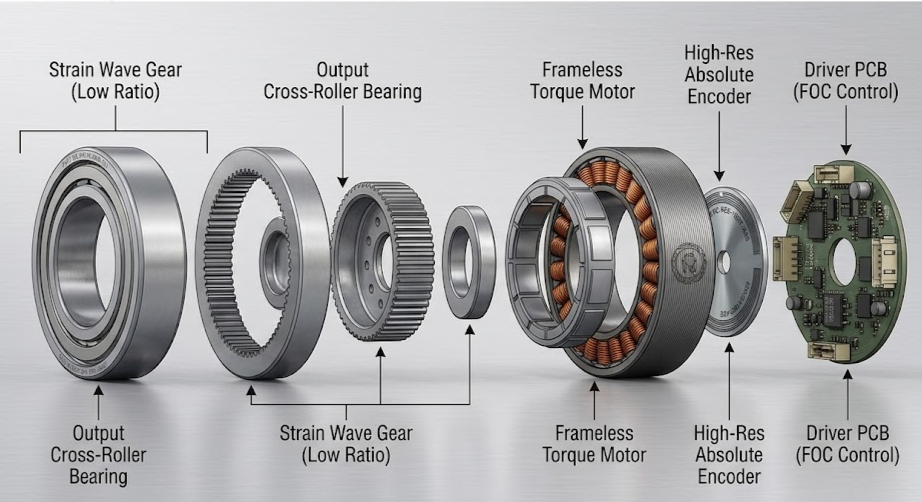
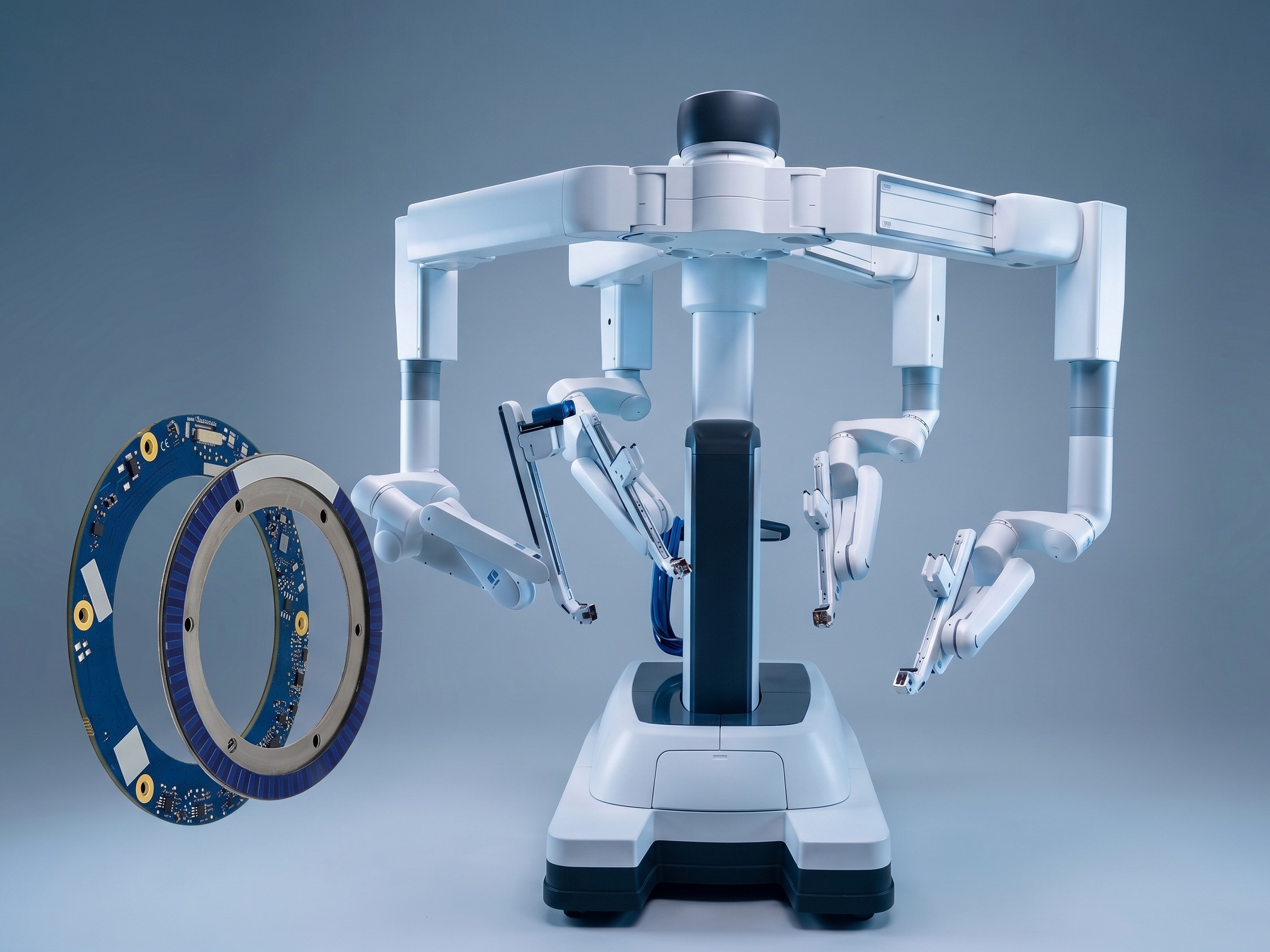
In minimally invasive surgical robotics, patient safety and clinical efficacy depend on position feedback systems capable of sub-arcsecond repeatability. Actuators in multi-axis robotic arms must translate clinician inputs into micro-movements inside the patient’s body with absolute fidelity. This demands a position encoder that can operate at the extreme limits of space, thermal dissipation, and electromagnetic noise.
Furthermore, modern surgical joints require large central through-bores (hollow shafts) to route high-definition stereoscopic camera fibers, pneumatic lines, saline irrigation, suction channels, and power cabling without twisting or mechanical binding. In this engineering guide, we examine how advanced inductive and Giant Magneto Impedance (GMI®) hollow-shaft encoders overcome the physical limits of traditional feedback systems in surgical motion control.
💡 Insight
Surgical joint design is a struggle against physics: actuators require zero-backlash, absolute startup position, zero thermal dissipation, and absolute EMI immunity, all within an ultra-flat form factor that accommodates a central through-bore.
1. Core Engineering Challenges in Robotic Joint Actuation
Integrating feedback sensors into surgical joints presents a series of conflicting requirements that standard industrial encoders cannot satisfy:
- The Hollow Shaft Bottleneck: Passing supply lines and optical cables through a joint requires a massive inner-to-outer diameter (ID/OD) ratio. Standard optical glass encoders are restricted by small bore sizes or suffer from large outer diameters that ruin the compact footprint of the joint.
- Thermal Constraints & Patient Safety: Actuators operating near the patient must maintain a low thermal signature. Any heat dissipation can damage tissue or create thermal expansion in the joint structures, degrading kinematic accuracy. Traditional optical encoders dissipate heat due to their continuous LED sources, whereas passive coil inductive systems remain completely thermal-neutral.
- Electrosurgical EMI: Surgical procedures frequently employ electrosurgical tools (RF monopolar/bipolar cauterization) that generate severe electrical noise and electromagnetic interference (EMI). A position encoder must maintain uninterrupted communication and signal integrity under these severe transients to prevent feedback failure or erratic movement.
2. FLUX GMI® & Inductive Technologies: Reimagining Feedback
FLUX GmbH has developed two distinct absolute encoder technologies that address these medical automation constraints:

Secure Your Components Stock Now with Torquety
Reliable automation components for high-performance applications.
A. Giant Magneto Impedance (GMI®) Technology
Developed and patented by FLUX, GMI® technology utilizes the high-frequency skin effect. A magnet ring mounted on the rotor produces a magnetic field that induces a localized alteration in the electrical impedance of a high-permeability GMI layer on the stator. By scanning this variable impedance, the encoder generates high-resolution signals in real-time.
Key Value: GMI® encoders deliver optical-grade performance (resolutions up to 23-bit, standard accuracies down to ±10 arcseconds (±0.003°), and zero hysteresis) combined with the ruggedness of an inductive sensor and the generous mounting tolerances of a magnetic encoder. Protected to IP67 standard, GMI-ROTARY encoders operate reliably in the presence of fluids and dust without compromises.
B. Inductive (IND-ROT & IND-ROT MINI) Technology
FLUX’s patent-pending inductive technology utilizes a planar stator board with printed coil structures that scan the absolute pattern of a lightweight rotor scale.
Key Value for Space Limits: The IND-ROT MINI Series (available in 34 mm, 36 mm, and 45 mm outer diameters) is currently the smallest and lightest absolute inductive encoder series on the market. With a total thickness of less than 6 mm and a total weight of just 14 grams (stator weights start at 3.5g; rotor weights at 5.5g), it is ideal for space-constrained robotic wrist joints. Furthermore, because of its passive inductive coil structure, it is 100% immune to external magnetic and electromagnetic fields. This allows it to be integrated directly inside motor frames adjacent to the windings without shielding.
“FLUX encoder technology bridges the gap between optical-grade precision and magnetic-grade robustness, delivering uncompromised absolute feedback in the most challenging medical and industrial motion control systems.”
3. The Power of 360° Holistic Scanning: Eliminating Eccentricity Error
Most conventional encoder technologies (such as Hall sensors, magnetic xMR, or optical segment sensors) rely on “one-point” or localized segment scanning. This makes them highly vulnerable to eccentricity error—the misalignment between the rotor’s geometric center and the axis of rotation.
Eccentricity occurs statically due to manufacturing or mounting tolerances, and dynamically due to external loading and gravitational forces acting on the robotic arm. For a single-point scanning encoder, the resulting eccentricity error (δ in arcseconds) is given by:
Where e represents the eccentricity displacement (half of the runout) in micrometers and D represents the encoder diameter in millimeters. As a result, a tiny 10 μm mounting misalignment on a 55 mm diameter joint causes an additional ±75 arcsecond error in a one-point encoder, rendering high-resolution feedback useless.
FLUX encoders overcome this limit through a holistic, 360° scanning principle. The stator scans the entire circumference of the rotor, inherently averaging out the signal. This cancels both static and dynamic eccentricity errors, providing major improvements in tracking accuracy:
| Diameter (OD) | Displacement (e) | One-Point Segment Encoder | FLUX IND-ROT (Inductive) | FLUX GMI-ROT (GMI) |
|---|---|---|---|---|
| 55 mm | 10 μm | ±75″ | < ±8″ | < ±4″ |
| 20 μm | ±150″ | < ±16″ | < ±6″ | |
| 69 mm | 10 μm | ±60″ | < ±6″ | < ±3″ |
| 20 μm | ±119″ | < ±12″ | < ±4″ | |
| 80 mm | 10 μm | ±52″ | < ±6″ | < ±3″ |
| 20 μm | ±103″ | < ±12″ | < ±4″ | |
| 96 mm | 10 μm | ±43″ | < ±5″ | < ±2″ |
| 20 μm | ±86″ | < ±10″ | < ±3″ |
4. Technology Comparison & Technical Capability Matrix
To guide design engineers in selecting the optimal motion feedback architecture, the following matrix compares traditional optical encoders with FLUX GMI and Inductive hollow-shaft series:
| Specification | Traditional Optical Glass Disc | FLUX GMI-ROT Series | FLUX IND-ROT (incl. MINI) |
|---|---|---|---|
| Measuring Principle | Optical slot scanning (Segmented) | Giant Magneto Impedance (360° scan) | Inductive Coil scanning (360° scan) |
| Available Sizes (OD) | Bulky, restricted size options | 55, 69, 80, 96, 150 mm | 34, 36, 45, 55, 69, 80, 96 mm |
| Through-Bore (Hollow Shaft) | Small or highly restricted bore size | Large through-bores (up to 100mm+) | Large through-bores (e.g. ø9mm on 34mm OD; ø17mm on 45mm OD) |
| Thickness / Stack Height | High thickness (typically > 20 mm) | Flat profile: 8 mm (incl. air gap) | Ultra-flat: < 6 mm (MINI series); 8 mm (Standard series) |
| Total Sensor Weight | Heavy (glass disks, heavy housing) | Lightweight (Al stator 22g-70g, rotor 8g-27g) | Ultra-light (MINI total: 14g; Standard stator 7g-12g, rotor 7g-18g) |
| Max Output Resolution | 16 to 22 bits | Up to 23 bits (Stable ENOB up to 22 bits) | Up to 22 bits (Standard) / 19 bits (MINI) |
| Repeatability | Slot resolution dependent | 1 resolution count | 1 resolution count |
| Hysteresis | None | None (Hysteresis-free) | None |
| Positional Accuracy | High under laboratory environment | High Accuracy option: ±8″ (150mm) to ±36″ (55mm); Standard: ±12″ to ±50″ | Standard: ±45″ (96mm) to ±90″ (55mm); MINI: ±90″ (34-45mm) achievable |
| Mounting Tolerances | Extremely tight (axial < 0.1 mm) | Liberal (axial 0.2 to 0.8 mm; radial runout 0.2 mm) | Wide (axial ±0.30 mm; radial ±0.30 mm / ±0.20 mm) |
| Ingress Protection (IP) | IP40 – IP50 (Very sensitive to dirt) | IP67 (Standard, potted design) | IP00 (Standard, conformal coating option) |
| Heat Dissipation | Significant (LED light source heat) | Low | Zero (Passive inductive coils) |
| EMI & EMC Immunity | Low to Moderate | High (Shielded digital lines) | Exceptional (100% immune to magnetic fields) |
| Field Calibration | Mandatory / Highly Complex | None (Plug-and-play) | None (Plug-and-play) |
5. Diagnostics & Plug-and-Play Assembly
Surgical robotic manufacturing requires streamlined assembly to keep production and quality assurance costs low. FLUX encoders require no field calibration or additional commissioning. Once mounted within tolerances, they provide high-accuracy positioning right out of the box.
To simplify integration and system diagnostics, the stators are equipped with a multi-color status LED (visible beneath the potting compound for GMI-ROT):
- Continuous Green: Optimal alignment, air gap, and performance.
- Blinking Green (fast/slow): Normal operation, but sub-optimal runout or air gap. This provides immediate visual feedback to technicians during joint assembly, allowing real-time adjustment.
- Continuous Yellow: Normal operation, but a historical error was detected (such as shielding issues or transient misalignments).
- Blinking Red (fast/slow): Out of operational range (air-gap violation) or configuration error.
This onboard diagnostic system ensures that joints can be verified and certified rapidly on the assembly floor, avoiding expensive diagnostic routines. Communication is supported over industry-standard digital protocols including BiSS-C (differential high-speed protocol for real-time control with low latency), SSI, and SPI.
Need a Custom Component Solution?
Contact our engineering team to discuss your application requirements and get a custom quote.