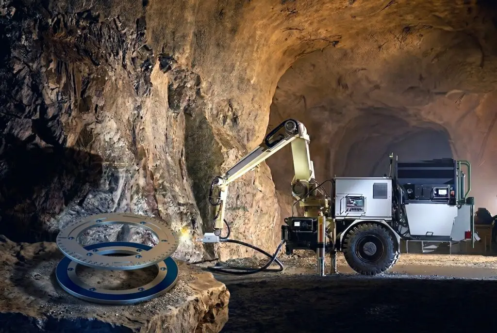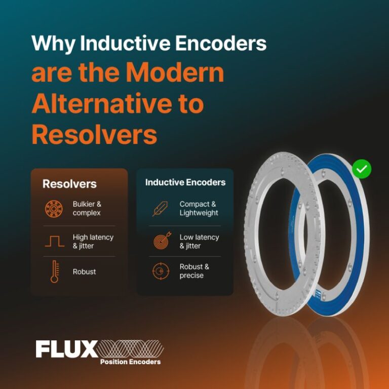
For decades, analog resolvers were the default choice for heavy industrial drives, mining equipment, aerospace actuators, and electric vehicles due to their mechanical robustness. However, resolvers offer limited resolution, require bulky copper windings, and demand expensive, space-consuming Resolver-to-Digital (R/D) conversion hardware inside the drive controller. Modern motion control systems require absolute precision, lightweight integration, and high bandwidth. As a result, design engineers are increasingly replacing resolvers with digital inductive encoders.
💡 Lead Editor’s Engineering Insight
By implementing a patent-pending inductive absolute technology, FLUX encoders deliver optical-grade precision (up to 23-bit resolution) with the rugged reliability of a resolver. Without the need for a separate Resolver-to-Digital converter, FLUX encoders transmit direct digital absolute position over BiSS-C or SSI protocols, eliminating latency, noise susceptibility, and system complexity.
The Core Limitations of Analog Resolvers
Resolvers operate as rotary transformers, utilizing primary and secondary copper windings on iron cores to generate analog Sine and Cosine voltage signals. While this copper-and-iron composition makes them highly resistant to extreme temperatures, shock, and vibration, it introduces significant technical drawbacks for high-performance motion control:
- The R/D Converter Bottleneck: Resolvers do not output digital position. They require a dedicated Resolver-to-Digital (R/D) converter circuit board at the drive level. This R/D converter adds hardware component costs, occupies valuable control cabinet space, introduces phase lag (signal latency), and limits the effective resolution (typically to 10–14 bits equivalent).
- Analog Noise Vulnerability: The low-voltage analog signals generated by resolvers must travel over long cabling runs in noisy industrial environments. Near high-power motor lines, these signals are highly susceptible to electromagnetic interference (EMI), causing position jitter, electrical noise, and tracking errors.
- Bulk, Weight, and High Cost: Heavy iron rotors and copper wound stators add significant inertia and weight (often hundreds of grams) to motor shafts. In robotic joints, surgical arms, and aerospace actuators, this added weight directly decreases payload capacity and dynamic responsiveness.
- Complex Calibration: Resolvers are highly sensitive to axial alignment. Achieving high accuracy requires manual alignment, mechanical phase calibration, and zero-point calibration during motor assembly.

Secure Your Components Stock Now with Torquety
Reliable automation components for high-performance applications.
The Alternative: FLUX Inductive Absolute Technology
FLUX has developed a patent-pending inductive absolute technology that allows for extreme compactness without sacrificing performance. The encoder consists of two main frameless components: an Encoder Stator (IRS/IMS) and an Encoder Rotor (IRR/IMR).
Unlike resolvers that rely on copper coils, the FLUX absolute inductive sensor scans the variable electrical impedance of an absolute metallic track pattern on the rotor. The integrated evaluation electronics directly on the stator PCB convert these impedance changes into a high-resolution, true absolute digital position.
This open, bearingless PCB architecture offers key integration advantages:
- Hollow Shaft & Frameless: Large through-holes allow cables, shafts, and slip rings to pass directly through the center of the encoder, which is essential for robotic joints and frameless direct-drive motors.
- Ultra-Flat Profile: With a thickness of less than 6 mm and an axial stack-up as thin as 8 mm (including the air-gap), FLUX encoders easily fit into the narrowest motor housings.
- Extreme Lightweight: The smallest standard inductive encoder (IND-ROT-034) weighs just 14 grams total (stator 3.5g, rotor 5.5g), drastically reducing rotational inertia compared to resolvers.
The 360° Holistic Scanning Advantage & Eccentricity Averaging
One of the primary engineering challenges in high-precision motion control is eccentricity—the physical offset between the geometric center of the encoder rotor and the motor’s actual axis of rotation.
Traditional optical or magnetic encoders use a “one-point” (segmental) scanning approach. In these systems, eccentricity introduces a sinusoidal positioning error over a complete rotation. The eccentricity error (δ) in arcseconds for a single-point scanning encoder is calculated as:
Where: δ is the eccentricity error in arcseconds, e is the radial eccentricity (half of the runout) in µm, and D is the encoder diameter in mm.
FLUX encoders employ a **holistic 360° scanning principle**, meaning the stator reads the entire circumference of the rotor simultaneously. By scanning 360°, the eccentricity error on one side of the disk is canceled out by the error on the opposite side. This inherent error averaging significantly reduces both static eccentricity (from mounting tolerances) and dynamic eccentricity (resulting from shaft deflection, thermal expansion, or vibration under load).
Comparison of Eccentricity-Induced Positioning Errors (δ)
| Encoder Outer Diameter (D) | Radial Eccentricity (e) | FLUX 360° Scanning Error | Conventional One-Point Error |
|---|---|---|---|
| 55 mm | 10 µm | < ± 8” | ± 75” |
| 55 mm | 20 µm | < ± 16” | ± 150” |
| 96 mm | 10 µm | < ± 5” | ± 43” |
| 96 mm | 20 µm | < ± 10” | ± 86” |
“By scanning 360° of the rotor pattern simultaneously, FLUX encoders inherently average out and compensate for static and dynamic eccentricity errors in real time—delivering uncompromised absolute feedback in the most challenging industrial environments.”
Selecting the Right FLUX Inductive Encoder for Your Application
To match the specific environmental and envelope demands of various industrial drives, FLUX offers two primary inductive encoder product lines:
1. IND-ROT Series (Standard & MINI)
The IND-ROT Series features an open-board PCB stator design, offering the absolute minimum weight and thickness. It is the premier choice for integration inside motor housings where space is extremely tight and extra weight cannot be tolerated:
- Compact Form Factor: Standard sizes range from 55 mm to 96 mm outer diameter, while the MINI series covers 34 mm, 36 mm, and 45 mm sizes.
- Lightweight Design: Standard stators weigh just 7g to 12g, and standard rotors weigh 7g to 18g. In the MINI range, a total encoder system weighs as little as 14g.
- Environmental Options: Open PCB design (IP00) rated for -20°C to +85°C, with extended operating temperature ranges up to +105°C and storage down to -55°C. Optional conformal coating provides excellent resistance to dust and condensation.
2. IND-MAX Series
The IND-MAX Series is built for extreme, heavy-duty applications across land, sea, and air. It features an encapsulated, rugged metal construction that matches or exceeds the durability of the toughest industrial resolvers:
- Sizes and Sturdiness: Available in larger diameters from 75 mm up to 375 mm, housed in anodized aluminum housings (with Option “N” for electroless nickel surface finishing for high marine corrosion resistance).
- IP67 / IP68 Ingress Protection: Standard IP67 rating, with Option “W” providing full IP68 water submersion protection.
- Extreme Pressure Rating (Subsea Actuation): With Option “H”, the IND-MAX can operate under pressures ranging from 0.05 to 200 bars. This makes it ideal for deep-sea subsea actuators and marine propulsion systems—eliminating the need for the heavy, oil-filled pressure-compensating enclosures required by resolvers.
- Extended Temperature Range: Under Option “E”, the operating temperature range spans from -45°C to +105°C, and storage spans from -55°C to +125°C.
- High Shock and Vibration Resistance: Engineered to withstand mechanical shocks of 200g (6 ms) and vibrations of 20g (55 to 2000 Hz).
Resolver vs. FLUX Digital Inductive Encoder Comparison
The table below compares the typical technical and operational performance of standard analog resolvers against FLUX’s digital inductive encoders:
| System Criterion | Traditional Analog Resolver | FLUX IND-ROT Series | FLUX IND-MAX Series |
|---|---|---|---|
| Output Interface | Analog Sin/Cos voltage signals | Digital Absolute (BiSS-C / SSI / SPI / Async) | Digital Absolute (BiSS-C / SSI / SPI / Async) |
| Resolution | 10 to 14 bits (dependent on external RDC) | Up to 22 bits | Up to 23 bits |
| Positional Accuracy | ±10 to ±20 arcminutes (±600″ to ±1200″) | ±45” to ±90” (±0.012° to ±0.025°) | Down to ±7” to ±10” (Grade G) |
| Drive Hardware Cost | High (requires dedicated R/D converter board) | None (direct microcontroller interface) | None (direct microcontroller interface) |
| Weight | Heavy (iron rotor, copper wound stator) | Ultra-lightweight (total weight starting at 14g) | Robust (housed, starting at 100g combined) |
| Ingress Protection | IP65 to IP67 (when encapsulated) | IP00 (open PCB, conformal coating optional) | IP67 / IP68 (Option W) |
| Subsea & Pressure Limit | Requires complex oil-filled housing compensation | N/A (open PCB) | Up to 200 bars (Option H subsea) |
| Hysteresis | Small (due to magnetic core behavior) | None (bearingless, direct scanning) | None (bearingless, direct scanning) |
| Mounting Tolerances | Tight axial alignment requirements | Liberal (axial ±0.30 mm, radial 0.30 mm) | Liberal (axial ±0.30 mm, radial 0.20 mm) |
| Calibration & Set-up | Time-consuming phase & zero-point tuning | Plug-and-play (no field calibration required) | Plug-and-play (no field calibration required) |
Need a Custom Component Solution?
Contact our engineering team to discuss your application requirements and get a custom quote.