Selecting the appropriate position feedback technology is one of the most critical decisions in closed-loop motion control. While optical encoders have traditionally dominated high-resolution applications, environmental contaminants, mechanical vibration, thermal expansion, and strict alignment constraints frequently lead to field failures. Modern inductive sensors and Giant Magneto Impedance (GMI®) encoders offer a groundbreaking alternative—combining optical-grade accuracy with absolute environmental immunity.
💡 Insight
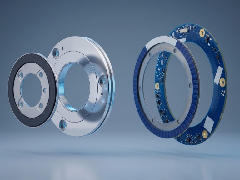
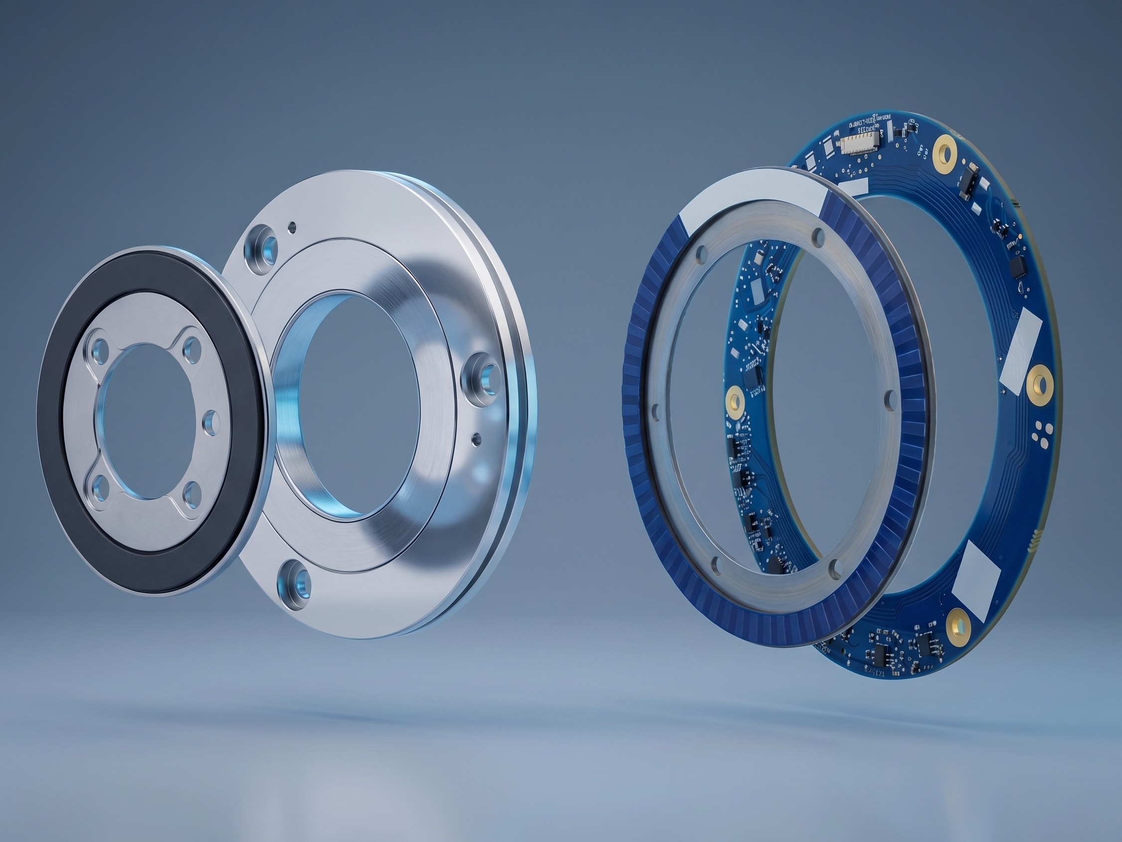
Traditional encoders scan position at a single point, making them vulnerable to shaft eccentricity and run-out. Modern electromagnetic encoders utilize a 360-degree holistic scanning approach. By reading changes in electromagnetic reluctance across the entire circumference of a hollow ring, local mounting imperfections, oil spray, and dust particles do not degrade the position reading.
The Five Core Sensing Technologies: How They Work
To design high-reliability motion control loops, engineers must understand the underlying physics of the primary feedback technologies. Each sensing method interacts differently with environmental factors, mechanical alignments, and external fields.
1. Optical Encoders
Optical encoders rely on photo-electric sensing. A light source (typically an LED) projects through a finely graded glass or plastic scale onto a photodetector array. As the rotor turns, the scale modulates the light beam to generate sine/cosine currents, which are then interpolated.
- Strengths: Outstanding resolution (up to 25+ bits) and high rotational accuracy; zero hysteresis due to direct optical reading.
- Weaknesses: High sensitivity to contamination. A single dust speck, oil film, or condensation droplet on the glass scale blocks the optical path, leading to immediate signal dropouts or tracking errors. They require sealed, bulky housings and tight axial alignment.
2. Magnetic Encoders
Magnetic encoders utilize Hall-effect or Magnetoresistive (AMR/GMR) sensors placed near a magnetized rotor track (containing alternating north and south poles). Rotation modifies the surrounding magnetic vector, changing the sensor’s electrical resistance.
- Strengths: Very robust against non-metallic dirt, dust, and moisture; simple mechanical structure and high-speed operation.
- Weaknesses: Sensitive to external magnetic and electromagnetic interference (EMI). Placing a magnetic encoder near high-current motor windings or brake magnets causes signal distortion. They also exhibit magnetic hysteresis and non-linearity errors.
3. Capacitive Encoders
Capacitive encoders measure shifts in capacitance between transmitter and receiver plates printed on circuit boards. A pattern-modulated rotor disc rotates between these plates, altering the dielectric path and shifting the capacitive coupling.
- Strengths: Flat mechanical profile, very low power consumption, and immune to magnetic fields.
- Weaknesses: Extremely sensitive to moisture, condensation, and electrostatic charges. Liquid ingress or relative humidity changes alter the local dielectric constant, generating severe signal drift or complete failure.
4. Inductive Encoders (FLUX IND Series)
Inductive encoders function on the principle of electromagnetic reluctance. An excitation coil on the stator (PCB) creates a high-frequency AC magnetic field. Receiver coils detect voltage changes induced by a structured metallic rotor scale. As the scale moves, the coupling inductances shift.
- Strengths: 100% immune to dust, grease, liquids, and moisture (IP67/IP68). Crucially, because they operate at high carrier frequencies with balanced PCB geometries, they are completely immune to magnetic and electromagnetic fields (EMI), allowing direct integration inside electric motor housings. Very flat (<6mm) and lightweight (14g).
- Weaknesses: Standard accuracy (±12 to ±90 arcseconds) is slightly lower than high-end optical glass scales, though sufficient for most servo loops and robotic joint controls.
5. GMI® Encoders (FLUX Patented GMI-ANG & GMI-ROT)
Giant Magneto Impedance (GMI®) technology utilizes the GMI effect, a high-frequency skin-effect phenomenon. The impedance of a specialized micro-wire element changes significantly when exposed to weak magnetic fields. FLUX encoders exploit this interaction to detect a scale’s position in real time.

Secure Your Components Stock Now with Torquety
Reliable automation components for high-performance applications.
- Strengths: Combines the best features of all systems. It delivers optical-grade accuracy (down to ±3 arcseconds) and high resolution (up to 25 bits) with the environmental ruggedness of inductive systems, large mounting tolerances (air gap up to 0.8mm), and zero hysteresis.
- Weaknesses: Requires a scale rotor and stator ring, but the frameless, bearingless design simplifies mechanical integration.
“FLUX patented GMI® and Inductive encoder technologies bridge the gap between optical-grade precision and magnetic-grade robustness, delivering uncompromised absolute feedback in the most challenging industrial, medical, and aerospace environments.”
The Geometry of Precision: 360° Holistic Scanning vs. Single-Point Encoders
A primary source of positioning error in rotary motion is eccentricity (radial run-out). Eccentricity occurs statically due to mounting tolerances (machining of the shaft, centering fit) and dynamically due to radial loads or vibration during operation.
Traditional optical or magnetic encoders use a “One-Point” scanning approach (a single sensor read-head aligned with one segment of the scale). Even a minuscule eccentricity of 10 to 20 µm generates massive positioning errors in single-point systems.
FLUX encoders scan the scale over the full 360-degree circumference. The receiver tracks are laid out holistically around the ring, mathematically averaging out eccentricity vectors. The following comparison shows the additional positioning error introduced exclusively by shaft eccentricity (e) in arcseconds (“):
| Scale Diameter (OD) | One-Point Scanning (e = 10 µm) | FLUX 360° Scanning (e = 10 µm) | One-Point Scanning (e = 20 µm) | FLUX 360° Scanning (e = 20 µm) |
|---|---|---|---|---|
| 55 mm | 75″ | < 4″ (GMI-ROT) / < 8″ (IND-ROT) | 150″ | < 6″ (GMI-ROT) / < 16″ (IND-ROT) |
| 69 mm | 60″ | < 3″ (GMI-ROT) / < 6″ (IND-ROT) | 119″ | < 4″ (GMI-ROT) / < 12″ (IND-ROT) |
| 80 mm | 52″ | < 3″ (GMI-ROT) / < 6″ (IND-ROT) | 103″ | < 4″ (GMI-ROT) / < 12″ (IND-ROT) |
| 96 mm | 43″ | < 1″ (GMI-ANG) / < 5″ (IND-ROT) | 86″ | < 2″ (GMI-ANG) / < 10″ (IND-ROT) |
| 160 mm | 26″ | < 1″ (GMI-ANG / IND-MAX) | 52″ | < 1″ (GMI-ANG / IND-MAX) |
Note: The 360-degree integration eliminates eccentricity-induced measurement drift, enabling engineers to achieve high accuracy even in systems with standard machining and assembly tolerances.
Comprehensive Technology Comparison Matrix
| Feature | Optical Encoders | Magnetic Encoders | Capacitive Encoders | FLUX Inductive & GMI® Encoders |
|---|---|---|---|---|
| Contamination Immunity | Low (Fails on dust, oil, grease, condensation) | Medium (Immune to non-metals; fails on metal dust) | Low (Highly sensitive to moisture, condensation) | 100% Immune (IP67/IP68 standard options; IND-ROT is IP00 open PCB but immune to fluid coatings) |
| Mechanical Profile | Bulky; requires protective housing & seals | Medium; requires specific air gap | Thin profile | Ultra-flat frameless ring (thickness < 6mm for IND-ROT; stack-up < 8mm for GMI) |
| Magnetic Fields (EMI) | Immune | Low (Easily distorted by motor fields, windings) | Immune | High (IND series is fully immune; GMI has shielded construction) |
| Thermal Stability | Medium (-10°C to +70°C typical) | Medium (-20°C to +85°C) | Low (Temperature affects dielectric air gap) | Extreme (-40°C to +105°C/+125°C operating; storage down to -55°C) |
| Hysteresis | Zero | High (Inherent to magnetic material cycle) | Low | Zero (No physical hysteresis; GMI & Inductive principles) |
| Mounting Tolerances | Very Tight (typically < 50 µm alignment) | Tight | Tight | Wide (Axial up to 0.8 mm; radial/runout up to 0.3 mm) |
| Wear & Maintenance | Medium (Bearings wear; optical scales age) | Low | Low | Zero (Bearingless design, frameless, maintenance-free) |
FLUX Position Feedback Portfolio: Technical Specifications
To match encoder models to specific closed-loop control applications, engineers can reference the physical properties, accuracies, and interface configurations of the core FLUX product lines.
| Series Name | Principle | Diameter (OD) Range | Max Resolution | Accuracy (High / Std) | Max Speed | IP Rating | Operating Temp |
|---|---|---|---|---|---|---|---|
| GMI-ANG | GMI® (Skin Effect) | 96 mm to 250 mm | 23 to 25 bits | ±3″ / ±4″ (250mm) ±5.5″ / ±7″ (160mm) | 2000 rpm | IP67 (Steel) | -40°C to +85°C (opt. to +125°C) |
| GMI-ROT | GMI® (Skin Effect) | 55 mm to 150 mm | 21 to 23 bits | ±8″ / ±12″ (150mm) ±36″ / ±50″ (55mm) | 6000 rpm | IP67 (Alu/Steel) | -40°C to +85°C (opt. to +125°C) |
| IND-MAX | Inductive (Reluctance) | 75 mm to 375 mm | 21 to 23 bits | ±7″ / ±10″ (375mm) ±18″ / ±36″ (75mm) | 6000 rpm | IP67 standard (opt. IP68 subsea) | -20°C to +85°C (opt. -45°C to +105°C) |
| IND-ROT | Inductive (Reluctance) | 55 mm to 96 mm | 21 to 22 bits | ±45″ / 0.012° (96mm) ±90″ / 0.025° (55mm) | 6000 rpm | IP00 (Open PCB) (opt. conformal coating) | -25°C to +85°C (opt. -40°C to +125°C) |
| IND-ROT MINI | Inductive (Reluctance) | 34 mm to 45 mm | 18 to 19 bits | ±90″ / 0.025° (45mm) ±180″ / 0.050° (34mm) | 6000 rpm | IP00 (Open PCB) | -25°C to +85°C (opt. -40°C to +125°C) |
Integration, Calibration, and On-Board Diagnostics
To reduce commissioning time and maintenance costs, FLUX designs physical interfaces that address field-service challenges directly:
1. Zero-Maintenance, Bearingless Design
Traditional enclosed encoders utilize internal bearings that wear out over time, especially under high shock and vibration. FLUX GMI and Inductive encoders consist of two separate components: a hollow rotor scale and a stator head. Because there is no physical contact between stator and rotor, there is zero friction, zero torque load on the motor, and zero mechanical wear, making the assembly completely maintenance-free.
2. Plug-and-Play Setup (No Field Calibration)
Optical and standard magnetic encoders require complex, time-consuming field calibration cycles using high-resolution oscilloscope benches to adjust signal gain, phase, and offset. FLUX encoders incorporate advanced real-time digital signal processing that dynamically compensates for run-out and mounting tolerances right out of the box. No field calibration is required.
3. On-Board Diagnostic LED Indicator
To verify proper mechanical alignment during assembly, FLUX stators feature an integrated multicolor status LED. This allows assembly technicians to verify structural alignment without checking software panels:
- Green (Continuous): Optimal performance. Nominal air gap and alignment achieved.
- Green (Blinking): Normal operation, but non-optimal performance (e.g., eccentricity/run-out detected). Check rotor alignment.
- Yellow (Continuous): Normal operation, but errors were detected and compensated. Check shielding connections or check rotor centering.
- Red (Slow Blinking): Out of operating range. Stator-to-rotor air gap is too wide or too narrow. Adjust mechanical spacing.
- Red (Continuous): System configuration error. Contact technical support.
4. Flexible Interface and Cabling Architecture
FLUX products support multiple digital communication interfaces: BiSS-C (up to 32-bit registers, including line delay compensation for long cables), SSI (Synchronous Serial Interface configurations SSI00 to SSI20), SPI (for direct microcontroller interfacing), Incremental TTL (A/B/Z), and UAT (Asynchronous UART).
Cables are optimized for different application environments:
- Option K01 (Integrated PUR): Halogen-free, suitable for cable carriers/energy chains. Rated for -40°C to +90°C dynamic bending.
- Option K02 (Silicone Rubber-based): Extremely high temperature and chemical resistance. Rated for -25°C to +180°C dynamic bending, and static down to -60°C. Features tinned copper braided shielding (95% coverage) to block high-frequency electromagnetic noise.
Selecting the Right Encoder for Your Application
Depending on the specific mechanical envelopes and ambient pressures, design engineers should map encoder lines to specific applications:
- Surgical Robotics & Exoskeletons: The **IND-ROT MINI (34mm to 45mm)** and **IND-ROT (55mm to 96mm)** open PCB lines are ideal. With a thickness under 6 mm and total weight of only 14 grams, they integrate directly inside compact joint actuators without loading the motor shaft.
- Frameless Torque Motors: **IND-ROT** and **IND-MAX** encoders integrate directly between motor windings. Their absolute immunity to magnetic and electrical fields ensures zero signal distortion even during peak current acceleration.
- High-Precision Gimbals & Stabilization: The **GMI-ANG (96mm to 250mm)** and **GMI-ROT (55mm to 150mm)** deliver sub-arcsecond repeatability, zero hysteresis, and high resolution (up to 25-bit), keeping stabilization loops stable and responsive.
- Subsea & Harsh Industrial Environments: The encapsulated **IND-MAX** series features IP67/IP68 sealing, high shock resistance (200g, 6ms), and high-pressure ratings (up to 200 bars), making them perfect for marine actuators, heavy tooling, and aerospace platforms.
Need a Custom Component Solution?
Contact our engineering team to discuss your application requirements and get a custom quote.