Before digital absolute encoders became available with the combination of high resolution, compact form, and digital output, resolvers were the standard position feedback device for high-performance servo motors in demanding environments.
Resolvers still remain the technology of choice for many applications above 150°C (aerospace actuation, gas turbine engines, engine bay automotive).
Under 150°C, modern digital encoders (particularly inductive and capacitive designs) offer equivalent durability with better resolution and direct digital output.
Resolver Operating Principle
A resolver is an electromagnetic transducer based on rotary transformer principles. It consists of:
- Rotor: A single-winding toroidal coil that rotates with the shaft
- Stator: Two windings arranged 90° apart in a fixed housing
Operation:
An AC excitation signal (typically 2–10 kHz, 3–7 Vrms) is applied to the rotor winding through a rotary transformer (no slip ring required). The stator windings inductively couple to the rotor winding with coupling coefficients proportional to the sine and cosine of the shaft angle:
- Stator winding 1 output: V₁ = V_exc × sin(ωt) × sin(θ)
- Stator winding 2 output: V₂ = V_exc × sin(ωt) × cos(θ)
A Resolver-to-Digital Converter (RDC) circuit at the controller processes V₁ and V₂ to compute θ.
Key properties:
- No active electronics in the sensor, the resolver is purely passive (wire windings on a ferromagnetic core)
- No semiconductor devices that fail at elevated temperature
- Excitation and signal levels are AC voltages, compatible with long cable runs and high-noise environments
Resolver Advantages Over Digital Encoders
Temperature Rating
Standard resolvers operate up to +155°C (Class F insulation) or +180°C (Class H insulation). High-temperature resolvers:
- Standard: up to +155°C
- Extended: up to +260°C
- Extreme: some designs rated above +300°C for jet engine applications
No semiconductor-based encoder (optical, inductive, capacitive, or magnetic) currently matches this temperature range. At +200°C and above, the resolver has no viable alternative for continuous operation.
Vibration and Shock Tolerance
The resolver’s passive, all-metal construction with wire windings is mechanically robust. Wound cores are not subject to the fatigue failure modes of semiconductor die attach, PCB traces, or optical elements. Military-grade resolvers are qualified to:
- Shock: 100 g, 11 ms
- Vibration: 50 g rms continuous
No Complexity on the Rotating Side
The resolver rotor is a simple winding, no electronics, no crystal, no active device. This simplicity means the rotating element can withstand environments that would damage any active electronic device.
Digital Encoder Advantages Over Resolvers
Resolution
A standard RDC converts resolver outputs to a 12–16 bit digital word. At 16-bit resolution (65,536 counts/rev), the angular resolution is approximately 0.0055° (20 arc-seconds).
Modern digital absolute encoders at equivalent form factor provide:
- Inductive: 22 bits (4 million counts/rev, 0.000086°)
- Capacitive: 26 bits (67 million counts/rev)
- Optical: 26+ bits
The (at least) 64× improvement in resolution (6 additional bits) is significant for precision servo applications.
Direct Digital Output
Resolvers require an Resolver to Digital Converter (RDC) at the drive/controller interface. The RDC:
- Adds cost to the system (specialized IC, typically $5–$30)
- Introduces conversion latency (typically 2–10 µs)
- Requires matched excitation frequency and amplitude
- Must be calibrated per resolver to minimize transformation error
Digital encoders provide a position word directly, no RDC required. The drive reads the position word via BiSS-C , SPI, SSI among others and uses it without additional signal processing.
Absolute Position at Power-Up
Standard resolvers (one-speed, single-turn) provide absolute position within ±180° , they cannot distinguish multiple revolutions. Multi-speed resolver pairs (a 1-speed resolver + an N-speed resolver) extend the range, but increase system complexity.
Digital absolute encoders provide power-up absolute position within their full absolute range (single-turn or multi-turn) without any additional hardware.
Size and Weight
Modern inductive and capacitive ring encoders achieve profile thicknesses of 3–10 mm. A resolver of equivalent capability is substantially thicker. For aircraft and automotive applications where weight and size are critical, this is a significant disadvantage.
Temperature Crossover: The Decision Boundary
| Operating Temperature | Technology Selection |
| > 180°C | Resolver (no digital encoder technology viable) |
| 125°C to 180°C | Resolver or high-temperature capacitive (VLT to +125°C); resolver preferred |
| 85°C to 125°C | Digital encoder (inductive, capacitive); resolver for extreme shock/vibration |
| < 85°C | Digital encoder preferred in almost all aspects |
The key specification to verify is the continuous operating temperature, not the peak or intermittent temperature. A servo motor in a machine tool environment may reach 80°C at the bearing housing during sustained operation. An encoder rated to +70°C would be operating outside its specification continuously.
Verifying the actual thermal environment and selecting an encoder with appropriate margin (at least +15°C above maximum expected temperature) prevents premature failure.
Resolver-to-Digital Converter Configuration
For existing systems using resolvers that are being upgraded:
The RDC inputs connect to the two stator output windings (sin, cos) and the reference signal (from the excitation source). Key configuration parameters:
- Reference frequency: Must match the excitation frequency used (2 kHz, 5 kHz, 10 kHz, most common)
- Reference amplitude: Typically 3–7 Vrms; the RDC has an input gain stage
- Velocity output: Many RDCs provide a velocity signal proportional to angular velocity. useful for direct velocity feedback to a servo velocity loop.
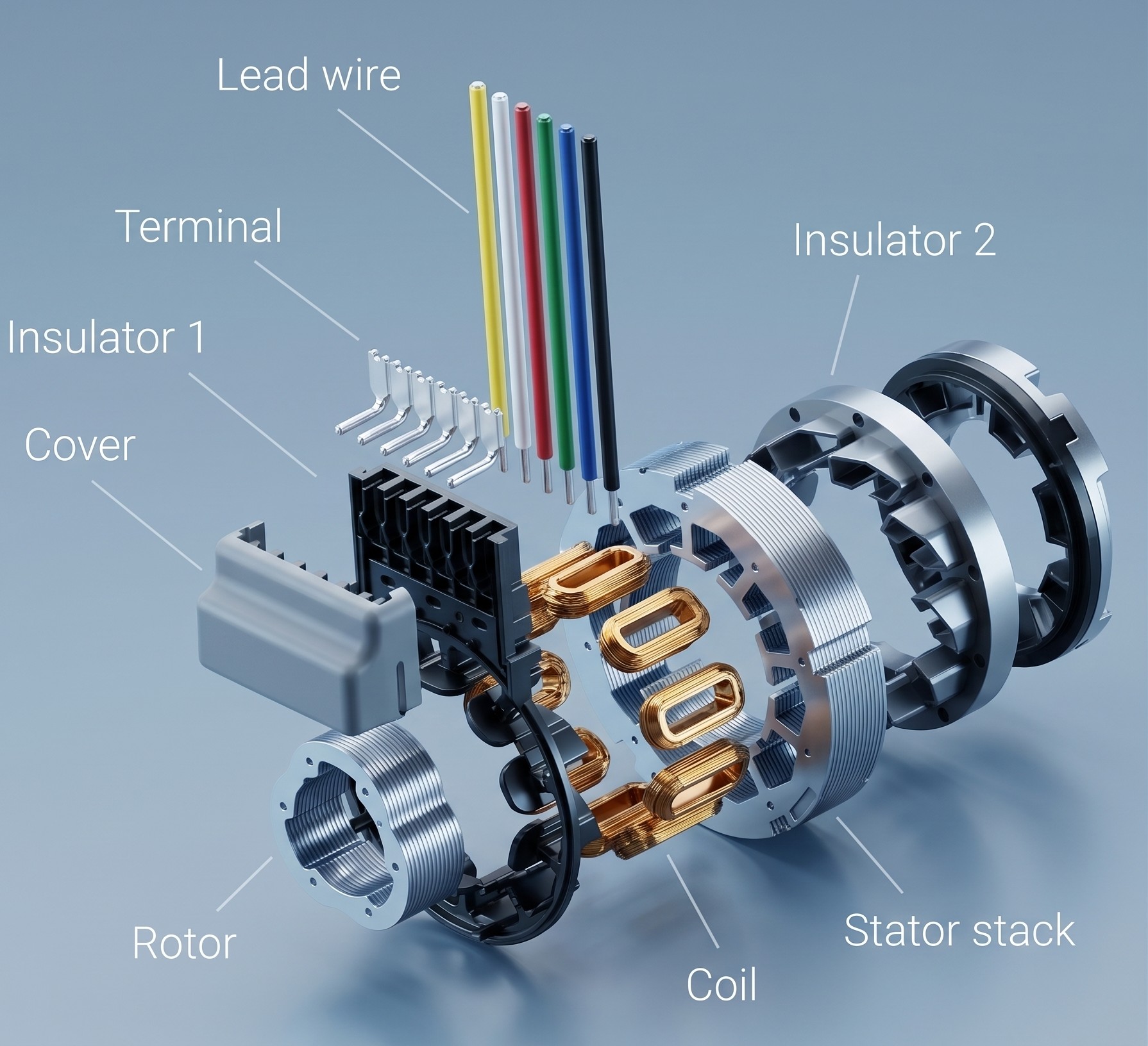
Figure 1: Variable Reluctance (VR) Resolver Construction: Exploded view showing the wound stator stack (carrying the excitation and sine/cosine coils) and the passive, winding-less shaped rotor. Reluctance variations in the air gap generate the sine and cosine output signals as the rotor rotates.
Source: Torquety
Typical High Temperature Applications for Resolvers
While the previous section established the temperature crossover boundary, it is essential to understand the specific industries and applications where resolvers remain irreplaceable due to sustained exposure to extreme heat. In these environments, no semiconductor-based encoder can operate continuously without failure.
The following table details the most common high-temperature applications where resolvers are the only viable position feedback technology:
| Application | Temperature Range | Why Resolvers Are Required |
| Jet engine fuel metering & variable stator vane actuation | 200°C – 300°C | Continuous exposure inside the engine nacelle. No semiconductor device survives above 200°C for sustained operation. Resolver windings use Class R (220°C) or Class C (>220°C) insulation. |
| Gas turbine power generation | 150°C – 250°C | Combined extreme temperature and heavy vibration from turbine rotation. Resolver all-metal construction withstands both simultaneously. |
| Automotive exhaust gas recirculation (EGR) valves | 150°C – 200°C | Mounted directly in the engine bay near exhaust manifolds. Cost-sensitive application where resolvers provide a simple, reliable solution. |
| Downhole drilling (oil & gas) | 175°C – 260°C | Extreme depth (3,000–7,000 m), no maintenance access, combined with high pressure (up to 30,000 psi). Requires custom high-temperature resolvers (e.g., Admotec Rotasyn series rated to 220°C). |
| Steel mill roll positioning | 150°C – 200°C | Radiant heat from molten steel, heavy mechanical shock from rolling operations, and conductive metal dust that would short-circuit PCB-based encoders. |
| Glass manufacturing kiln drives | 180°C – 260°C | Continuous operation in close proximity to glass melting furnaces. Requires custom resolvers with Class R or Class C insulation and ceramic-coated windings. |
| Nuclear reactor control rod positioning | 150°C – 200°C + radiation | Ionizing radiation degrades semiconductor devices over time (total ionizing dose effect). Resolver wire windings and ferromagnetic cores are radiation-tolerant. |
| Industrial furnace damper control | 200°C – 300°C | Combustion zone proximity. Requires custom high-temperature resolvers with Class C insulation. Resolver excitation signals are immune to the intense electromagnetic noise from heating elements. |
Typical Low Temperature Applications for Resolvers
Extreme cold presents unique challenges for position feedback devices. At temperatures below -40°C, many semiconductor devices exhibit increased leakage current, threshold voltage shifts, and eventual failure. Battery-powered electronics become unreliable as electrochemical reactions slow dramatically. Resolvers, being purely passive electromagnetic devices, maintain their performance across the full temperature spectrum.

Secure Your Components Stock Now with Torquety
Reliable automation components for high-performance applications.
| Application | Temperature Range | Why Resolvers Are Required |
| Arctic/polar military vehicles & weapons systems | -55°C to -40°C | MIL-STD-810 requires operation to -51°C (storage to -62°C). Resolver passive windings are unaffected by extreme cold. No semiconductor junction to freeze out. |
| Space mechanisms (satellite antenna drives, solar array drives) | -65°C (eclipse) to +125°C (sun) | Rapid thermal cycling (100°C+ swing per orbit), vacuum, and cosmic radiation. Resolvers qualified to ESA ECSS standards for space-grade actuation. |
| Cryogenic valve actuators (LNG, liquid O₂, liquid N₂) | -162°C to -196°C | No commercial semiconductor encoder is rated below -55°C. Requires custom cryogenic-rated resolvers with specialized insulation materials and thermal contraction management. |
| High-altitude UAV and aircraft actuators | -55°C at cruise altitude | Rapid thermal cycling from ground level (+40°C) to high altitude (-55°C) within minutes. Resolver thermal mass and passive construction handle this without failure. |
| Antarctic and polar research station equipment | -60°C ambient | Extended maintenance cycles (equipment may be unserviceable for months). Resolver zero-maintenance passive design is ideal. |
| Submarine periscope and mast drives | -40°C to +70°C (arctic operations) | Combined cold temperature, pressure, humidity, and vibration. Resolver IP67-rated housings with passive internals provide decades of service life. |
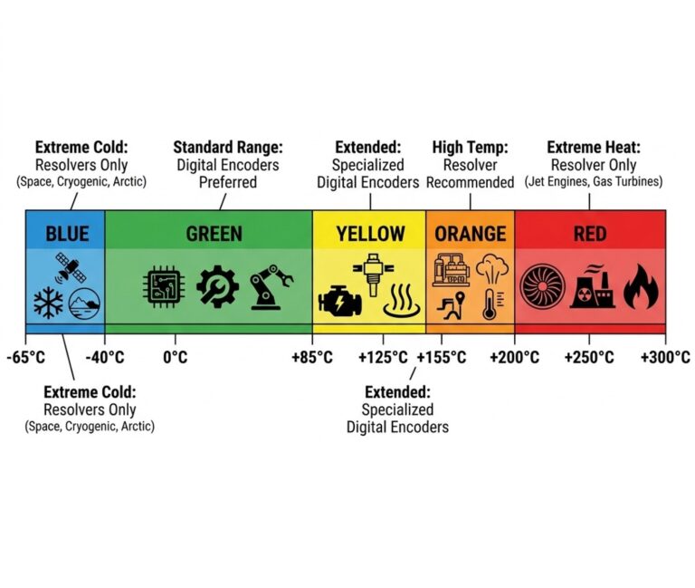
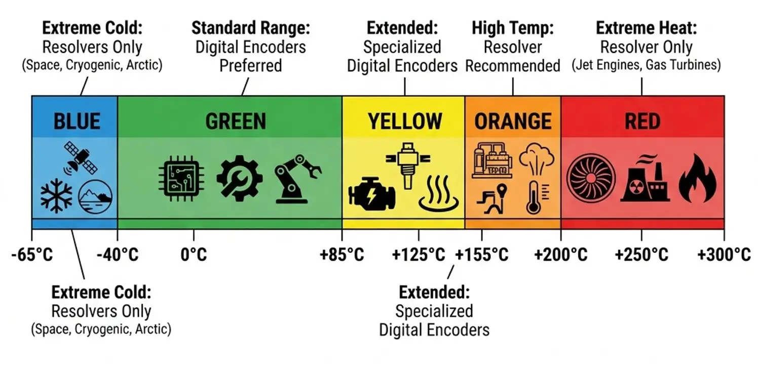
Figure 2: Temperature Operating Zones, Resolver vs. Digital Encoder Selection Guide. Blue: extreme cold (resolvers only). Green: standard range (digital preferred). Yellow/Orange: extended range. Red: extreme heat (resolvers only).
Source: Torquety
Resolvers and Safety: The Unhackable Advantage
In an era of increasing cybersecurity threats to industrial and defense systems, the resolver offers a unique and often overlooked advantage: it is fundamentally immune to cyberattack.
No Computer, No Firmware, No Hack
A resolver is a purely passive electromagnetic device, wire windings on a ferromagnetic core. It contains:
• No microprocessor
• No firmware or software
• No flash memory or EEPROM
• No digital communication protocol
• No operating system
Because there is no computational element in the sensor, there is no attack surface. A resolver cannot be reprogrammed, spoofed via protocol injection, or compromised through supply chain firmware tampering. This is not a security feature that was designed in, it is an inherent property of the technology.
Defense and Military Implications
Modern digital encoders contain onboard microprocessors running firmware, communicating via digital protocols (BiSS-C, SSI, EnDat, Hiperface). While these protocols are not typically networked, they represent a theoretical attack vector in high-security environments:
• Firmware manipulation: A compromised encoder firmware could report incorrect position data, causing a weapons system to miss its target or an aircraft control surface to malfunction.
• Protocol injection: A malicious actor could intercept or inject data on the digital communication line between encoder and drive.
• Supply chain attack: An encoder with pre-installed malicious firmware could be introduced during manufacturing or logistics.
For this reason, resolvers remain the mandated position feedback device in many military applications:
• Missile guidance fin actuation (MIL-R-23417 qualified resolvers)
• Naval weapons system turret drives
• Radar antenna positioning systems
• Fighter jet flight control surface actuators
• Armored vehicle turret and gun elevation drives
Safety-Critical Certification
Beyond cybersecurity, resolvers align naturally with functional safety standards:
• IEC 61508 (SIL): The resolver signal path is purely analog and deterministic, there are no complex software elements requiring extensive V&V (Verification and Validation).
• ISO 26262 (Automotive): ASIL-D rated systems (electric power steering, brake-by-wire) frequently use resolvers because the failure modes are well-characterized and predictable.
• DO-178C (Aerospace): Avionics position feedback systems requiring DO-178C software certification can avoid the complexity by using resolvers instead of firmware-based encoders.
The Digital-to-Sine/Cosine Conversion Problem: A Common Engineering Mistake
One of the most common (and most problematic) approaches to migrating from resolvers to digital encoders is the “digital-to-analog conversion” route. This section explains why this approach should be avoided.
The Popular Approach
Many servo drives in the installed base were designed with resolver inputs only, they expect sine/cosine analog signals. When engineers want to upgrade to a digital encoder for better resolution, they often take the following approach:
• Install a digital absolute encoder (e.g., with BiSS-C or SSI output)
• Add a Digital-to-Analog Converter (DAC) module
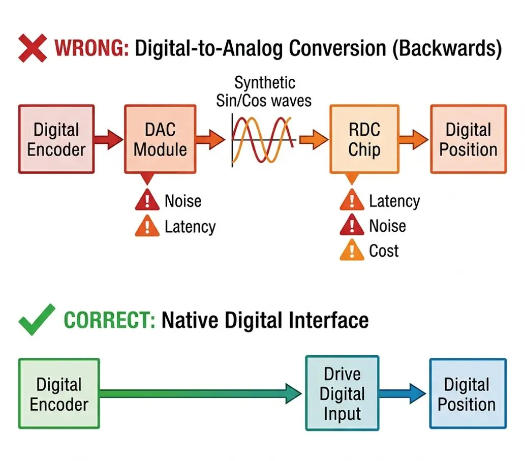
• The DAC synthesizes artificial sine and cosine signals from the digital position data
• Feed these synthetic sine/cosine signals into the drive’s resolver input
On paper, this makes the digital encoder “look like” a resolver to the drive. In practice, this approach introduces serious problems:
Why The Approach May Fail
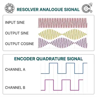
1. Noise Amplification: The D/A conversion introduces quantization noise. The reconstructed sine/cosine waveforms are stepped approximations, continuous curves that a real resolver produces (as compared to the digital square-wave quadrature signals shown in Figure 3. This stepped signal introduces harmonic distortion that propagates directly into the servo loop, causing torque ripple and position jitter.
2. Reduced Reliability: The conversion module adds components (DAC IC, operational amplifiers, precision voltage references, filter capacitors) that can each fail independently. Each added component reduces the overall system Mean Time Between Failures (MTBF).
3. Added Latency: The digital-to-analog conversion introduces processing delay. In high-bandwidth servo loops (>1 kHz), even microseconds of additional latency can degrade phase margin and cause instability.
4. Loss of Resolution: A typical DAC module outputs 12-bit or 14-bit sine/cosine signals. If the original digital encoder provides 22-bit resolution, the DAC throws away 8–10 bits of precision, defeating the purpose of upgrading to a digital encoder.
5. Unnecessary Cost: The encoder itself has a cost, and the DAC module adds significant additional expense, plus engineering time for integration, calibration, and testing.
Figure 3: Waveform Comparison, Top: Amplitude-modulated analog resolver signals showing the high-frequency input excitation carrier and the modulated sine and cosine outputs representing the shaft angle. Bottom: Digital incremental encoder quadrature signals (Channel A and Channel B square waves) offset by 90° electrical phase.
Source: Torquety
Figure 4: Signal Path Comparison, The backwards approach (digital → DAC → synthetic sin/cos → RDC → digital) vs. the correct approach (digital encoder → native digital interface → drive). Each conversion step adds noise, latency, and cost.
Source: Torquety
The Safest Approach
Instead of converting digital signals back to analog, the correct engineering approach is to use a servo drive that natively supports digital encoder protocols:
| Protocol | Type | Typical Resolution | Max Cable Length | Key Advantage |
| BiSS-C | Synchronous serial | Up to 32-bit | ~100 m | Open standard, high speed, widely supported |
| SSI | Synchronous serial | Up to 25-bit | ~100–300 m (frequency dependent) | Simple, long cable runs, widely supported |
| EnDat 2.2 | Synchronous serial | Up to 29-bit | ~100 m | Bidirectional, diagnostic data, Heidenhain standard |
| Hiperface DSL | Single-cable | Up to 24-bit | ~100 m | Power + data on motor cable, SICK standard |
| SPI | Synchronous serial | Up to 25-bit | ~2 m | Direct connection, very high speed, short distance |
By selecting a drive with a native digital interface, the engineer preserves the full digital resolution, eliminates all analog conversion artifacts, and reduces system complexity and cost.
How to Analyze if Your Controller Can Read a Specific Encoder
Before selecting an encoder, the engineer must verify that the servo drive (controller) can actually read the encoder’s output. An incompatible encoder-drive combination will result in zero position feedback, the motor will not operate in closed-loop mode.
The following checklist provides a systematic approach to verifying encoder-drive compatibility:
| Parameter to Verify | Where to Find It | What to Check |
| Supported feedback type | Drive datasheet → “Feedback Input” or “Encoder Interface” section | Does the drive support: Resolver, Incremental (A/B/Z), Sine/Cosine 1Vpp, SSI, BiSS-C, EnDat 2.1/2.2, Hiperface, SPI? The encoder’s output must match one of these. |
| Excitation frequency (resolver only) | Drive manual → “Resolver Configuration” parameters | The drive’s excitation frequency must match the resolver’s rated frequency. Common values: 2 kHz, 5 kHz, 10 kHz. Mismatch causes signal distortion. |
| Excitation voltage (resolver only) | Drive manual → “Resolver Configuration” parameters | Typically 3–7 Vrms. The drive must supply the voltage the resolver is designed for. |
| Maximum resolution supported | Drive datasheet → “Encoder Input Specifications” | If the encoder provides 22-bit resolution but the drive only supports up to 16-bit, the extra bits are discarded. Verify the drive supports the encoder’s full bit depth. |
| Protocol version | Drive firmware release notes or configuration software | BiSS-C vs. BiSS-B, EnDat 2.1 vs. 2.2, Hiperface vs. Hiperface DSL, the specific protocol version must match. Newer versions are not always backward compatible. |
| Supply voltage to encoder | Drive encoder connector pinout diagram | Most encoders require 5V DC supply. Some require 3.3V or a specific voltage range. The drive’s encoder port must supply the correct voltage. |
| Cable length | Drive installation manual → “Encoder Wiring” section | Digital protocols have maximum cable length limits. BiSS-C: ~100 m. SSI: ~100–300 m (depends on clock frequency). SPI: ~2 m. Verify the installation distance is within limits. |
| Multi-turn support | Drive configuration software → “Encoder Setup” | If using a multi-turn absolute encoder, the drive must support multi-turn data. Some drives only accept single-turn position words. |
| Encoder power consumption | Encoder datasheet → “Electrical Specifications” | The drive’s encoder supply must provide sufficient current. Typical: 50–200 mA. If the encoder draws more than the drive can supply, use an external power supply. |
Need Help Selecting the Right Position Feedback Solution?
Whether your application demands the extreme temperature tolerance of a resolver or the high-resolution digital output of a modern inductive encoder, Torquety’s engineering team can help you specify, source, and integrate the optimal solution.
Contact Torquety today: contact@torquety.com
Need a Custom Component Solution?
Contact our engineering team to discuss your application requirements and get a custom quote.