High-Performance Encoders for Motion Systems
Integrates the high accuracy and robustness of inductive technology with the wide alignment tolerances of magnetic systems.
Represented in the UK by Torquety, FLUX designs and manufactures high-performance frameless hollow-shaft encoders, engineered specifically for mechatronic developers, robotic designers, control engineers, and aerospace system integrators. By operating with a unique 360° holistic scanning geometry, FLUX systems inherently eliminate eccentricity errors, simplifying closed-loop motion control in the most demanding physical environments.
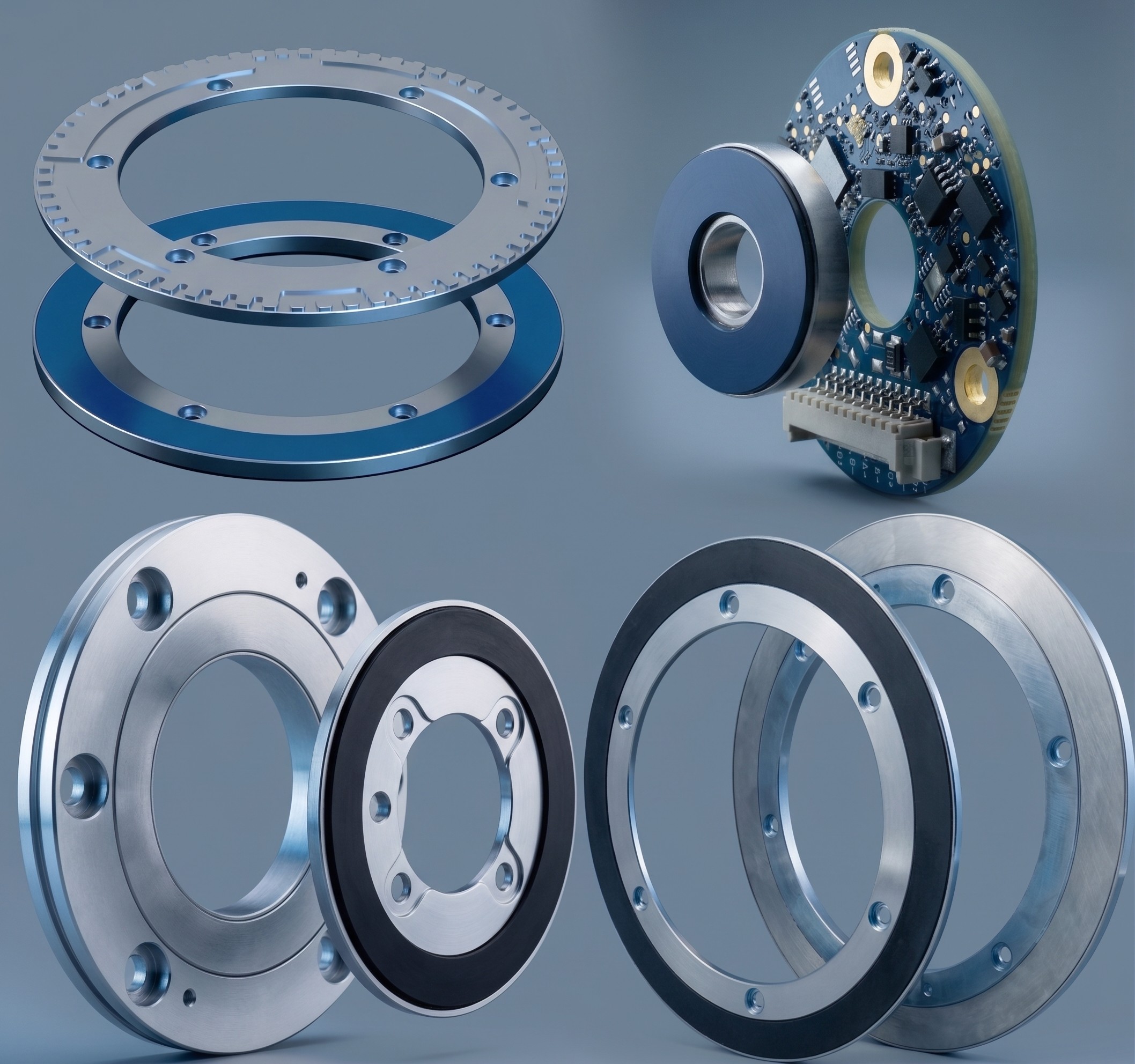

Engineered to Solve Encoder Constraints
FLUX overcomes the traditional trade-off between installation complexity, physical ruggedness, and accuracy.
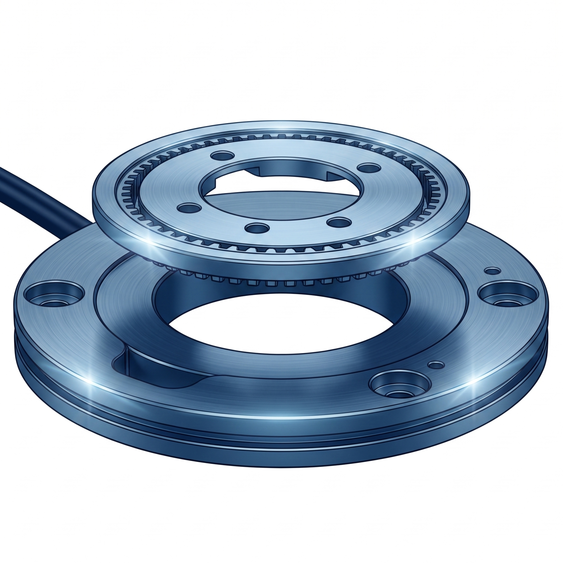
Patented GMI® Technology
Giant Magneto Impedance (GMI®) technology utilizes the electromagnetic skin effect in specialized materials. The sensor determines the relative position of the scale with zero hysteresis and high resolution (up to 25 bits), providing real-time data under IP67 protection.
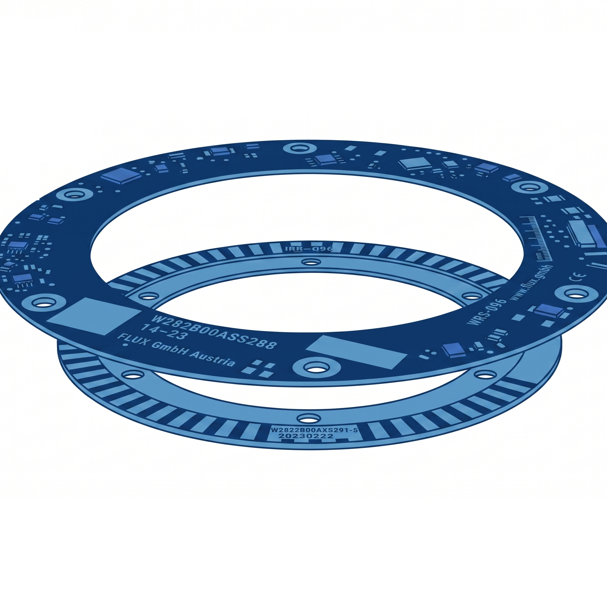
Advanced Inductive Scanning
Patent-pending absolute inductive technology provides high-precision position feedback in the smallest physical footprint. Complete immunity to stray magnetic fields and electromagnetic interference allows direct motor integration without shielding.
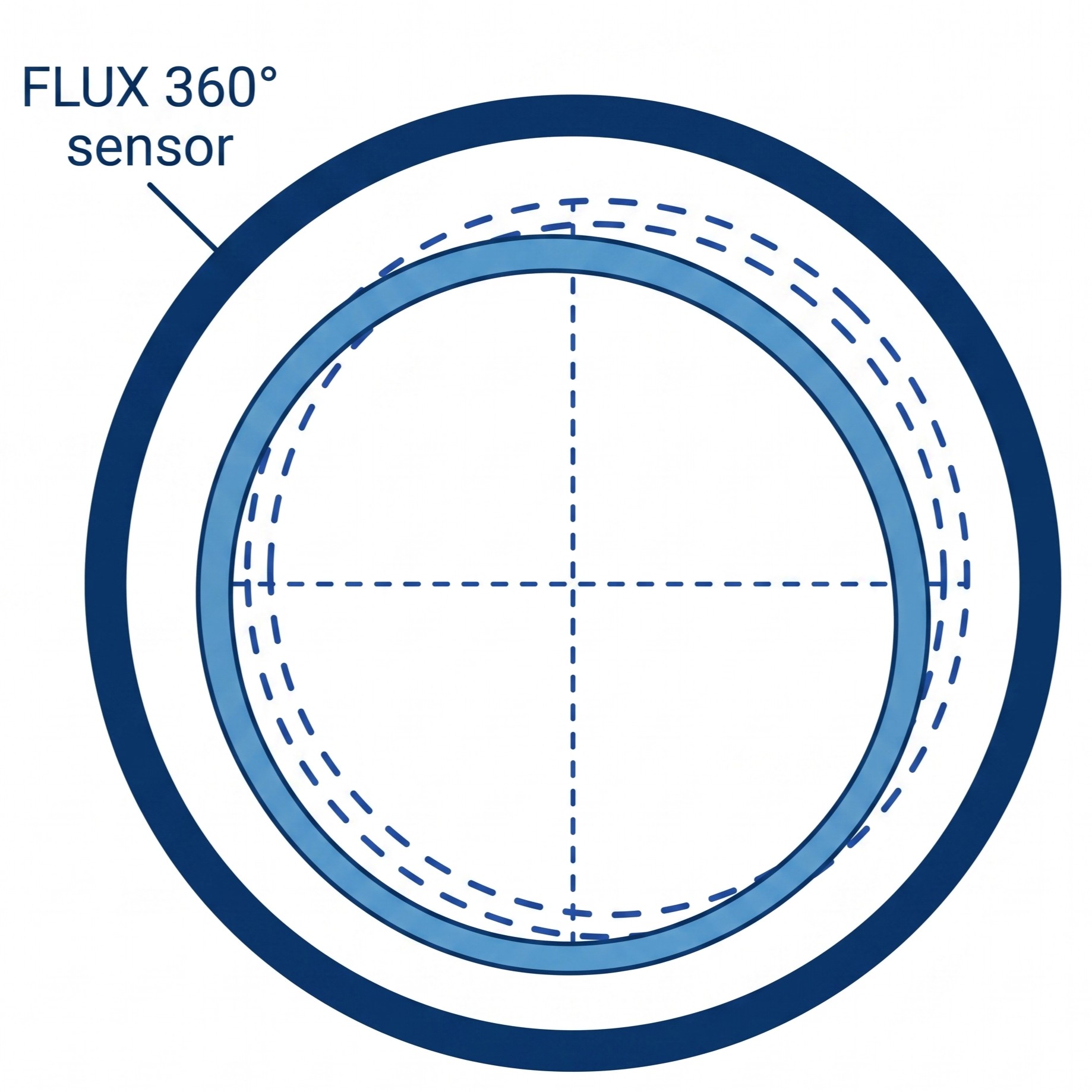
360° Holistic Scanning
Instead of single-point or segment reading, FLUX encoders scan the full 360° circumference. This holistic scanning averages out static alignment run-out and operational axis shifts, neutralizing eccentricity errors.
The Physics of Eccentricity Error Correction
In conventional single-point encoders, rotor eccentricity (misalignment between geometric and rotational centers, denoted as (e)) introduces significant angular errors. The static or dynamic eccentricity error in arcseconds is defined by:
FLUX’s 360° holistic scanning continuously averages signals from the entire circumference, reducing eccentricity-induced angular errors to virtually zero.
Angular Error under Misalignment (Single-Point vs. FLUX 360° Scanners)
| Encoder Size / Diameter (D) | Error with Eccentricity (e = 10 mutext{m}) | Error with Eccentricity (e = 20 mutext{m}) |
|---|---|---|
| GMI (96 mm) | FLUX: < ±1″ (Single-Point: ±43″) | FLUX: < ±2″ (Single-Point: ±86″) |
| GMI (160 mm) | FLUX: < ±1″ (Single-Point: ±26″) | FLUX: < ±1″ (Single-Point: ±52″) |
| GMI (180 mm) | FLUX: < ±1″ (Single-Point: ±23″) | FLUX: < ±1″ (Single-Point: ±46″) |
| GMI (250 mm) | FLUX: < ±1″ (Single-Point: ±16″) | FLUX: < ±1″ (Single-Point: ±32″) |
Frameless Absolute Encoders Portfolio
GMI-ANG Series • High Accuracy Angle Encoders
High-precision rotary axes, CNC machine tool tables, and calibration systems require absolute positioning feedback with sub-arcsecond repeatability. Under dynamic operating conditions, standard encoders face structural strain and misalignment, causing thermal drift and measurement errors.
Traditional optical encoders offer high accuracy but are highly susceptible to dust, condensation, and mechanical shock, and require complex mounting setups with precise alignments. FLUX GMI-ANG series addresses this vulnerability by utilizing patented GMI® technology to deliver optical-grade accuracy combined with the physical ruggedness of an inductive sensor and generous mounting tolerances.
Featuring a bearingless, frameless design with a generous hollow shaft, the GMI-ANG encoders are built into a heavy-duty stainless steel housing. The integration is simplified with sliding fits, and an onboard alignment LED provides real-time feedback on installation quality.
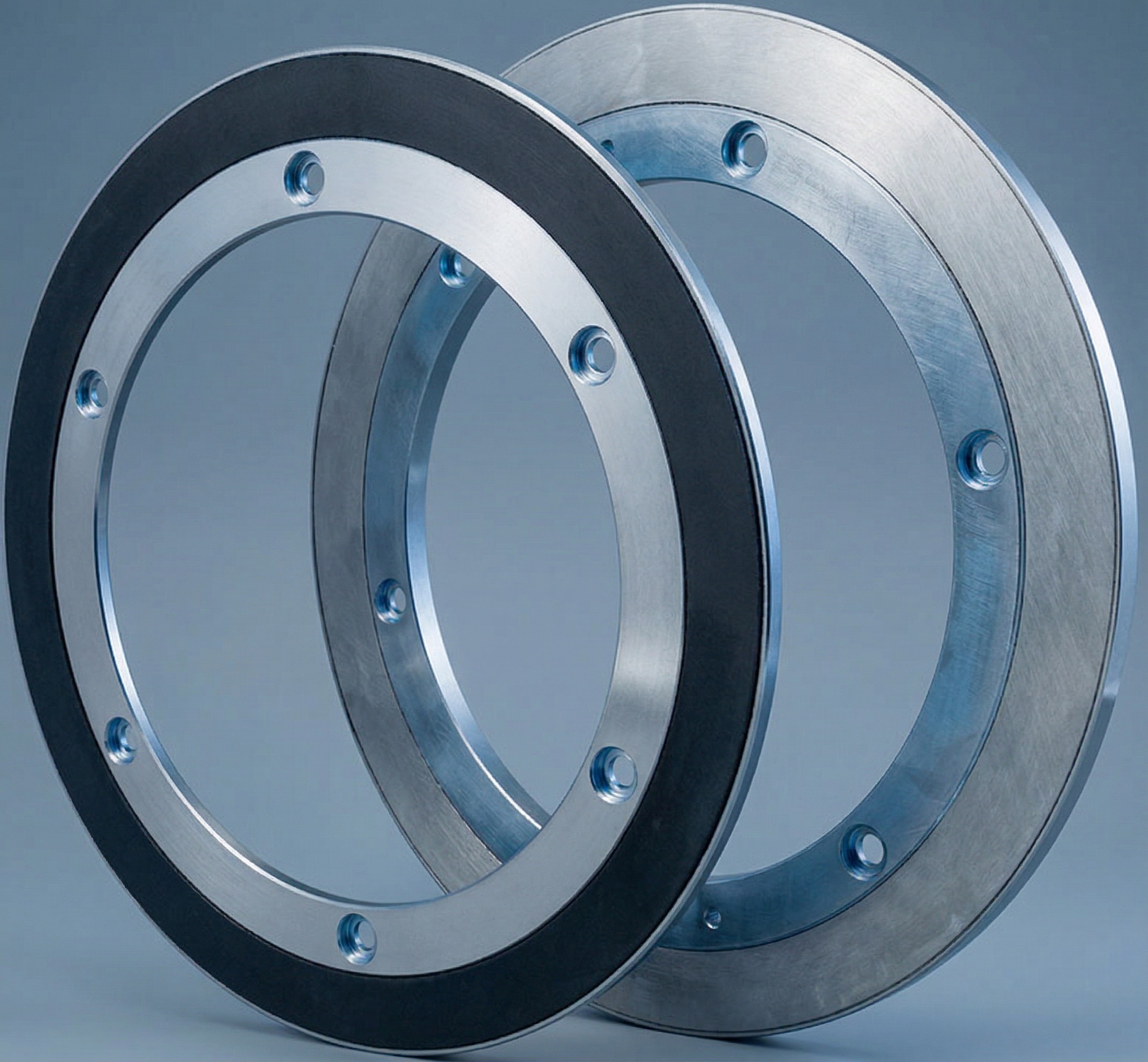
Technical Specifications:
| Model | Outer Diameter | Stator ID / Rotor ID | Max Resolution | Standard Accuracy | High Accuracy (Opt C) |
|---|---|---|---|---|---|
| GMI-ANG-096 | 96 mm | 50 mm / 35 mm | 23-bit | ±14″ | ±8″ |
| GMI-ANG-160 | 160 mm | 110 mm / 110 mm | 24-bit | ±7″ | ±5.5″ |
| GMI-ANG-180 | 180 mm | 130 mm / 110 mm | 24-bit | ±7″ | ±5.5″ |
| GMI-ANG-250 | 250 mm | 200 mm / 180 mm | 25-bit | ±4″ | ±3″ |
* Standard operating specifications: 2,000 rpm max speed, nominal air-gap 0.30 mm (±0.25 mm tolerance), 4.35 to 36 Vdc supply with reverse polarity protection, IP67 protection, vibration 20G, shock 200G.
GMI-ROT Series • Precision Rotary Encoders
Modern collaborative robot (cobot) joints, compact satellite communication (satcom) gimbals, and surgical robotic systems demand extremely flat feedback devices. These systems require high resolution and repeatability to maintain smooth velocity control and precise trajectories in highly space-constrained environments.
Standard optical and magnetic encoders are often too thick, require dedicated bearings, or suffer from signal latency and hysteresis during direction changes. The FLUX GMI-ROT series provides a compact, frameless rotary solution that operates without hysteresis, providing real-time absolute position updates at high resolution up to 23 bits.
Built with an axial installation profile of just 8 mm, the GMI-ROT series offers rotor mounting variations (internal, external, or radial clamping) in either lightweight anodized aluminum or high-strength steel housings. The non-contact design permits wide axial air-gap tolerances from 0.20 to 0.80 mm.
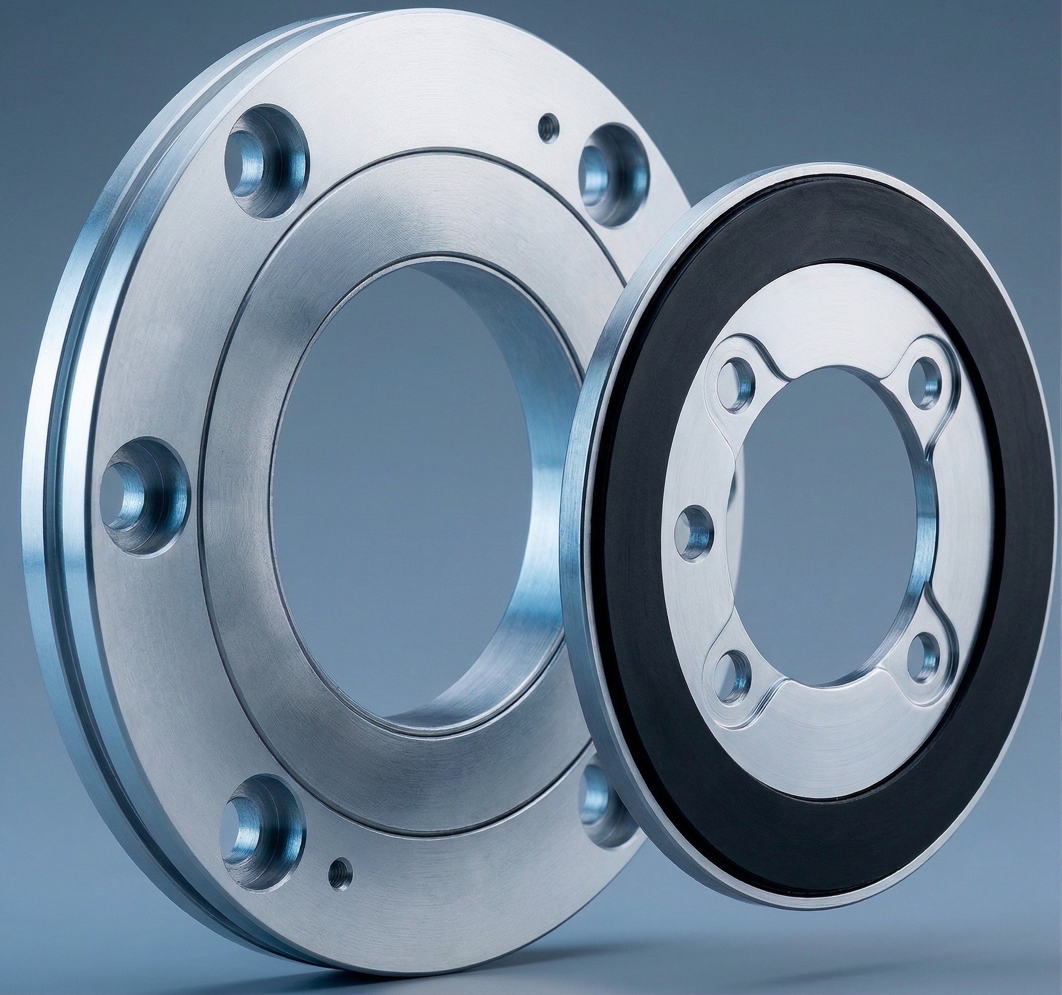
Technical Specifications:
| Model | Outer Diameter | Stator ID / Rotor ID | Max Resolution | Standard Accuracy | High Accuracy (Opt C) |
|---|---|---|---|---|---|
| GMI-ROT-055 | 55 mm | 26.20 mm / 17 mm (A11) or 25 mm (B11) | 21-bit | ±50″ | ±36″ |
| GMI-ROT-069 | 69 mm | 40.20 mm / 29 mm (A11) or 39 mm (B11) | 22-bit | ±36″ | ±29″ |
| GMI-ROT-080 | 80 mm | 51.20 mm / 40 mm (A11) or 50 mm (B11) | 23-bit | ±25″ | ±14″ |
| GMI-ROT-096 | 96 mm | 67.20 mm / 56 mm (A11) or 66 mm (B11) | 23-bit | ±18″ | ±10″ |
| GMI-ROT-120 (OEM) | 120 mm | Custom OEM | 22-bit | Custom OEM | Custom OEM |
| GMI-ROT-150 | 150 mm | 121.20 mm / 110 mm (A11) or 120 mm (B11) | 23-bit | ±12″ | ±8″ |
* Standard operating specifications: 6,000 rpm max speed, nominal air-gap 0.30 mm (0.10-0.80 mm range), 4.35 to 36 Vdc supply, IP67 protection, available in Anodized Aluminum (AL) or Stainless Steel (ST).
IND-ROT Series • Inductive Flat Rotary Encoders
Compact mechatronic actuators, exoskeletons, and mechatronic grippers operate under severe space and weight restrictions. Feedback sensors integrated into these systems must add minimal weight while remaining completely immune to stray magnetic fields from nearby motor coils.
Traditional magnetic encoders are disrupted by magnetic stray fields from high-power density motors, while optical encoders are too bulky and fragile for wearable or high-vibration applications. The FLUX IND-ROT series solves this constraint by utilizing a patent-pending inductive absolute scanning principle that is completely immune to electromagnetic interference.
Consisting of an ultra-lightweight open PCB stator and a stainless steel or aluminum rotor, the IND-ROT series features a thickness below 6 mm and a total weight of just 9 g to 30 g. The bearingless, non-contact design ensures a maintenance-free lifetime with generous mounting tolerances.
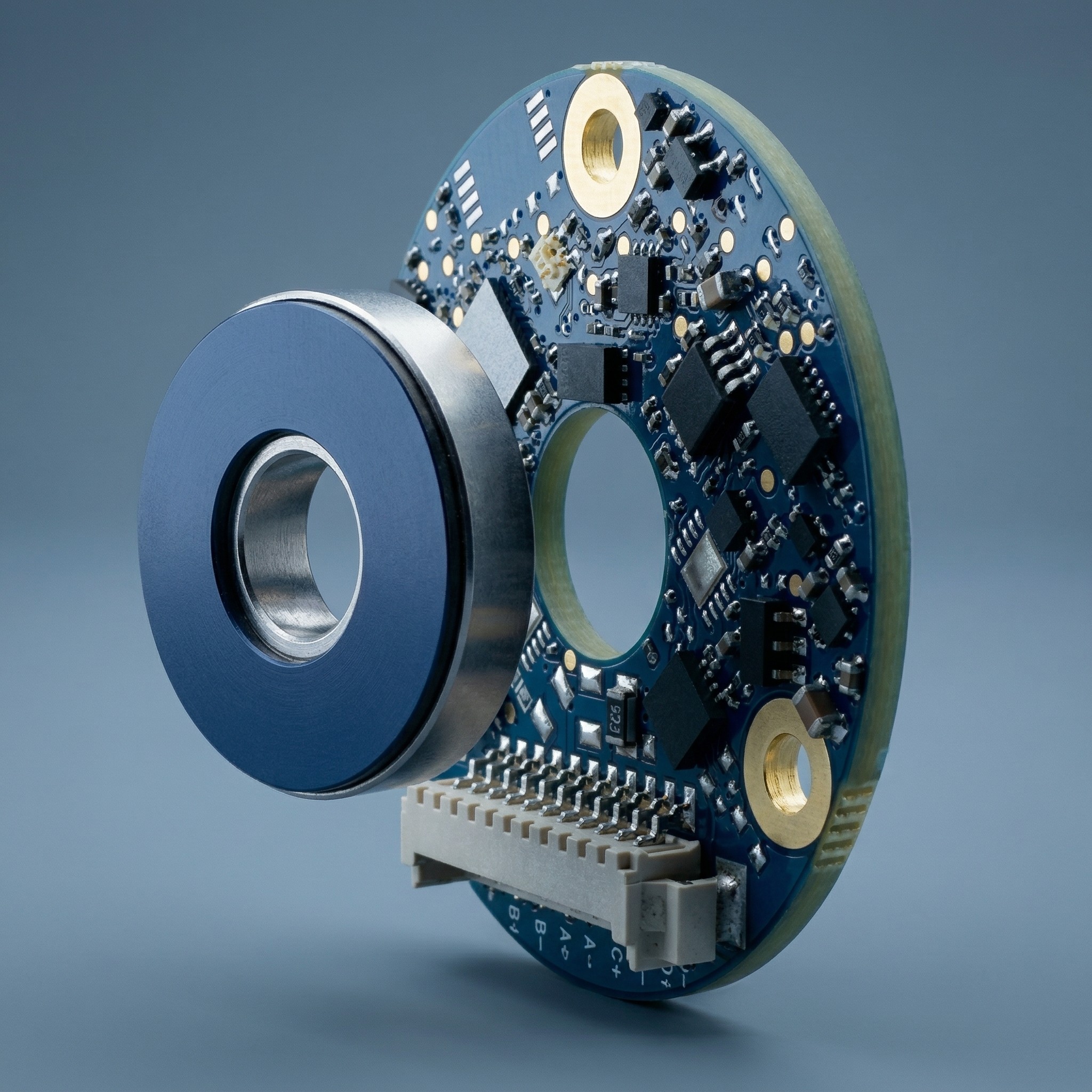
Technical Specifications:
| Model | Outer Diameter | Stator ID / Rotor ID (A21) | Max Resolution | Standard Accuracy | Max Achievable Accuracy |
|---|---|---|---|---|---|
| IND-ROT-034 (MINI) | 34 mm | 9 mm / 8 mm | 18-bit | ±0.050° (±180″) | ±0.030° (±108″) |
| IND-ROT-036 (MINI) | 36 mm | 11 mm / 8 mm | 19-bit | ±0.040° (±144″) | ±0.025° (±90″) |
| IND-ROT-045 (MINI) | 45 mm | 17 mm / 8 mm | 19-bit | ±0.040° (±144″) | ±0.025° (±90″) |
| IND-ROT-055 (Std) | 55 mm | 26 mm / 17 mm | 21-bit | ±0.025° (±90″) | — |
| IND-ROT-069 (Std) | 69 mm | 40 mm / 29 mm | 21-bit | ±0.020° (±75″) | — |
| IND-ROT-080 (Std) | 80 mm | 51 mm / 40 mm | 21-bit | ±0.018° (±65″) | — |
| IND-ROT-096 (Std) | 96 mm | 67 mm / 56 mm | 22-bit | ±0.012° (±45″) | — |
* Standard operating specifications: IP00 open PCB design (acrylic conformal coating optional), nominal air-gap 0.50 mm (0.20-0.80 mm range), 4.35 to 36 Vdc supply for MINI and 5 V for Standard, 6,000 rpm max speed, operating temp -20° to +85°C (extended to +105°C optional).
IND-MAX Series • Rugged Inductive Encoders
Unmanned aerial vehicles (UAVs), tactical defense gimbals, naval radar mounts, and heavy heavy-duty machinery operate in extreme environments subject to heavy rain, dirt, and severe vibration. Positioning feedback systems in these applications must guarantee absolute reliability and high precision despite temperature fluctuations and mechanical shock.
Conventional absolute encoders are prone to physical wear or sealing degradation under exposure to mud, saltwater, and high-G forces, leading to sensor failures. The FLUX IND-MAX series overcomes these challenges by using an inductive absolute technology encapsulated in a rugged IP67-rated housing, providing high-precision feedback under severe conditions.
The IND-MAX series is housed in anodized aluminum with optional electroless nickel plating, delivering high rigidity in a hollow-shaft, frameless design. It supports high operating temperatures from -45°C to +105°C and can withstand vibrations up to 20G and mechanical shocks of 200G.
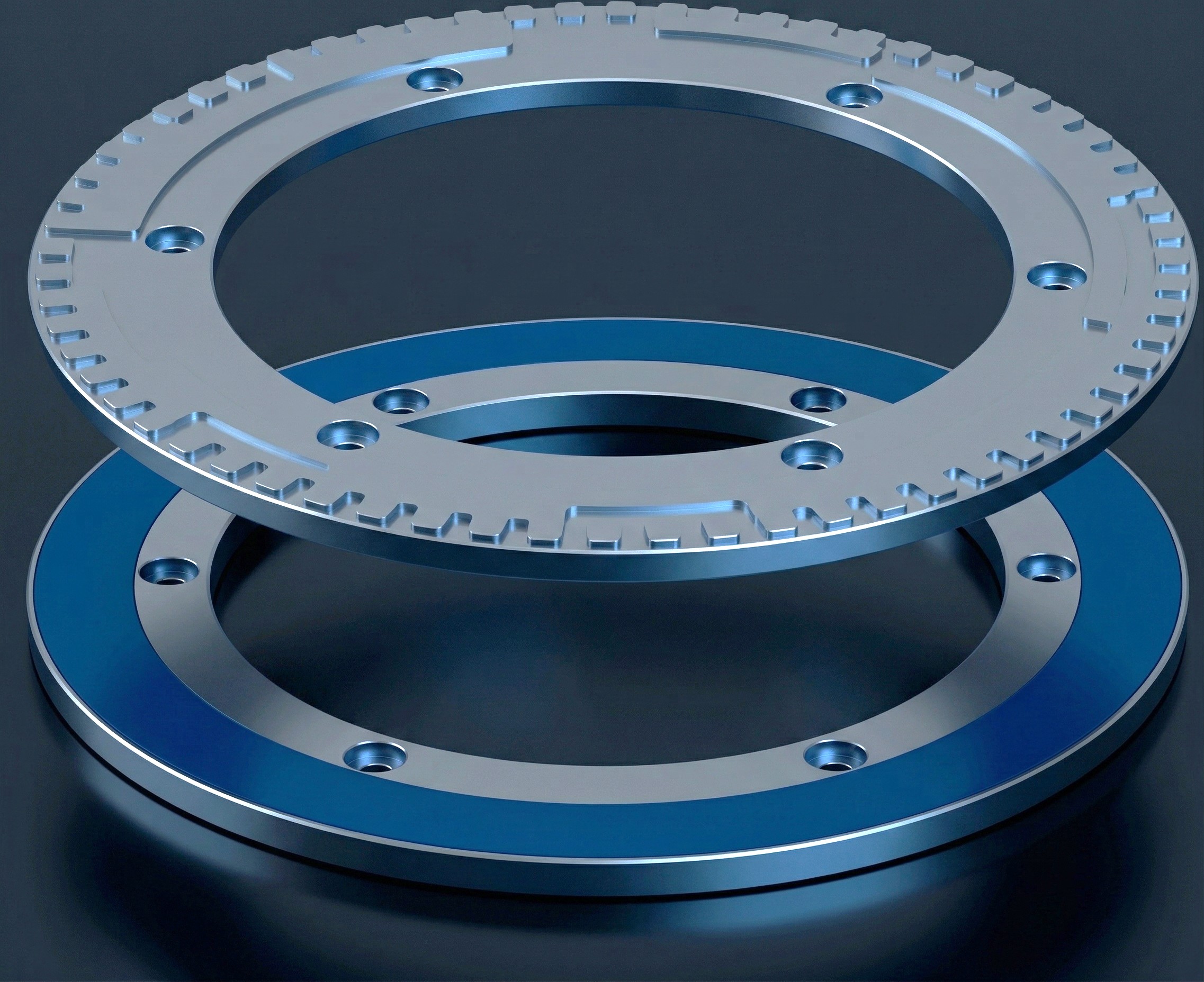
Technical Specifications:
| Model | Outer Diameter | Stator ID / Rotor ID | Max Resolution | Accuracy Grades |
|---|---|---|---|---|
| IND-MAX-075 | 75 mm | 25.80 mm / 25 mm | 23-bit | Grade B / C / D (down to ±36″) |
| IND-MAX-100 | 100 mm | 50.80 mm / 50 mm | 22-bit | Grade B / C / D / E (down to ±18″) |
| IND-MAX-125 | 125 mm | 75 mm / 75 mm | 21-bit | Grade B / C / D / E (down to ±18″) |
| IND-MAX-160 | 160 mm | 110 mm / 110 mm | 23-bit | Grade B / C / D / E (down to ±18″) |
| IND-MAX-180 | 180 mm | 130 mm / 110 mm | 23-bit | Grade B / C / D / E (down to ±18″) |
| IND-MAX-200 | 200 mm | 150 mm / 150 mm | 23-bit | Grade C / D / E / F (down to ±14″) |
| IND-MAX-250 | 250 mm | 200 mm / 180 mm | 23-bit | Grade C / D / E / F / G (down to ±7″) |
| IND-MAX-300 | 300 mm | 250 mm / 250 mm | 23-bit | Grade C / D / E / F / G (down to ±7″) |
| IND-MAX-375 | 375 mm | 325 mm / 325 mm | 23-bit | Grade C / D / E / F / G (down to ±7″) |
* Standard operating specifications: IP67 sealing (upgradeable to IP68), air-gap nominal 0.50 mm (reduced to 0.35 mm for Grade G with high-accuracy Option C), 6,000 rpm max speed, EMI compliance EN IEC 61000-6-2/4.
IND-MAX Marine Grade • Subsea Position Encoders
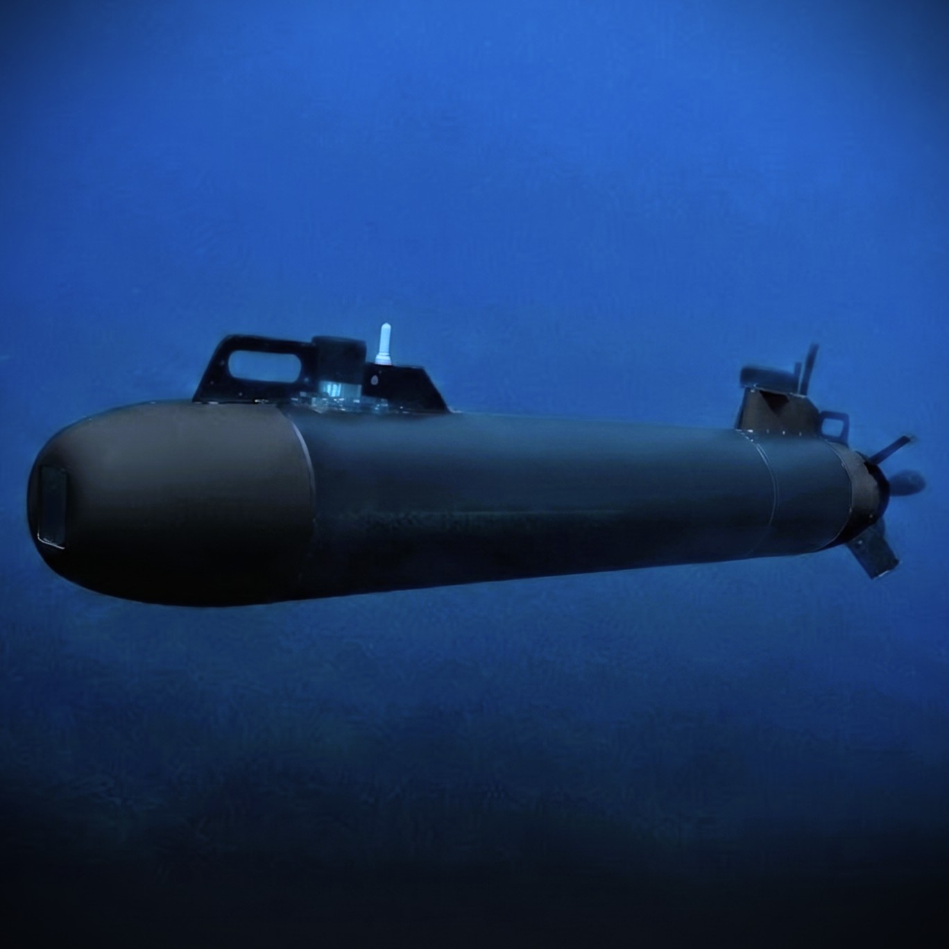
Offshore oil and gas platforms, underwater ROVs/AUVs, azimuth thrusters, and deck winches operate under constant exposure to high salinity, corrosive galvanic action, and immense pressure. Position feedback sensors in these applications must resist chemical degradation while maintaining absolute accuracy during long-term immersion.
Standard industrial encoders quickly corrode in saltwater or leak under hydraulic pressure, requiring frequent and costly replacements. The FLUX IND-MAX-100 Marine Grade resolves this issue by combining the electromagnetic immunity of 360° inductive scanning with a fully sealed, marine-grade stainless steel enclosure.
Sealed to IP68/IP69K for permanent submersion and high-pressure washdowns, this Marine Grade version features extreme temperature tolerances and an optional rating for pressure resistance up to 200 bar. The housing design eliminates cathodic corrosion risks and is immune to high electrical noise from massive naval generators.
Technical Specifications:
| Model | Outer Diameter | Stator ID / Rotor ID | Max Resolution | Accuracy Grades | Sealing Class |
|---|---|---|---|---|---|
| IND-MAX-100-Marine | 100 mm | 50.80 mm / 50 mm | 22-bit | Grade B / C / D / E (down to ±18″) | IP68 / IP69K (Subsea) |
* Standard operating specifications: 200 bar high pressure option, storage temperature -55°C to +100°C, full marine-grade anodized aluminum construction, 360° scanning.
Communication Interfaces & Pinouts
FLUX encoders support a wide range of standard protocols for direct integration with control systems.
Absolute Serial Protocols
BiSS-C (Bidirectional Synchronous Serial): Designed for real-time high-speed data transmission. Includes status flags (Error, Warning) and 6-bit CRC checking. Clock rates up to 5 MHz are supported with line delay compensation for cable runs over 3 meters.
- BIS00: 32-bit position, right-aligned. (Recommended for linear systems).
- BIS10: 24-bit position, left-aligned. (Recommended for rotary systems up to 24-bit).
- BIS20: 32-bit position, left-aligned. (Recommended for rotary systems 25-bit and higher).
SSI (Synchronous Serial Interface): Unidirectional protocol using RS-422 differential signals. Supported options include SSI00 (Error, Warning, and Even Parity), SSI01 (Raw position data transmission), SSI02 (SPI master compatible in Mode 2), SSI03 (Virtual Multi-Turn configuration with 46-bit transmission), SSI04 (24-bit transmission containing 22 right-aligned position data bits and 1 active-low Error status bit (nE)), and SSI11 (Position data transmission with no status bits in the data frame).
Asynchronous & Incremental Protocols
UART (UATxx Series): Asynchronous serial data is transmitted continuously over differential RS-485/RS-422 lines without a clock signal. Available baud rates are: UAT00: Operating at 230.4 kbps (230,400 bps) with a 2.5 kHz frame cycle. UAT01: Operating at 921.6 kbps (921,600 bps) with a 10.0 kHz frame cycle. UAT10: Supported on select models (GMI-ANG and IND-MAX) for custom asynchronous communications.
Incremental A/B/Z (INCxx Series): Dual square waves phase-shifted by 90° electrical with a differential Z index channel (RS-422 / TTL).
- INC00: 5.0 MHz maximum frequency before quadrature evaluation (20M counts/sec). Supports speeds up to 4,577 rpm at 18-bit resolution, or 6,000 rpm at 14-bit resolution.
- INC01: 2.5 MHz maximum frequency before quadrature.
Connector Pinout Tables
IND-ROT MINI Series (11-Pin, 1.25mm Pitch)
| Pin | SSI / BiSS-C | Incremental | Description |
|---|---|---|---|
| 1 | VDD | VDD | Supply Voltage (4.35-36 Vdc) |
| 2 | GND | GND | Power Ground |
| 3 | NC | B+ | Incremental B (+) |
| 4 | NC | B- | Incremental B (-) |
| 5 | NC | A+ | Incremental A (+) |
| 6 | NC | A- | Incremental A (-) |
| 7 | SCLK+ | NC | Sync Clock (+) |
| 8 | SCLK- | NC | Sync Clock (-) |
| 9 | SDATA+ / TX+ | Z+ | Data (+) / Serial TX (+) / Index (+) |
| 10 | SDATA- / TX- | Z- | Data (-) / Serial TX (-) / Index (-) |
| 11 | SHIELD | SHIELD | Cable Ground Shield |
IND-ROT Standard Series (10-Pin, 0.80mm Pitch)
| Pin | SSI / BiSS-C | Incremental | UART |
|---|---|---|---|
| 1 | VDD | VDD | VDD |
| 2 | GND | GND | GND |
| 3 | NC | B+ | NC |
| 4 | NC | B- | NC |
| 5 | NC | A+ | NC |
| 6 | NC | A- | NC |
| 7 | SCLK+ | NC | NC |
| 8 | SCLK- | NC | NC |
| 9 | SDATA+ | Z+ | TX+ |
| 10 | SDATA- | Z- | TX- |
Frequently Asked Questions
Comprehensive specifications, mounting tolerances, protocols, and integration guidelines for FLUX inductive encoders.
Category 1: Core Technology & Competitive Advantages
How does FLUX patented GMI® technology compare to optical and magnetic encoders?
Traditional optical encoders offer high accuracy but rely on delicate glass scales and fine gratings that fail under dust, moisture, condensation, or high shock/vibration. Traditional magnetic encoders offer physical ruggedness but suffer from magnetic hysteresis, lower resolution, and severe sensitivity to stray electromagnetic fields from motor coils.
FLUX’s patented Giant Magneto Impedance (GMI®) technology leverages the high-frequency electromagnetic skin effect in specialized amorphous materials. This enables optical-grade accuracy (up to ±3 arcseconds) and high resolution (up to 25-bit) combined with the physical ruggedness of an inductive sensor, zero hysteresis, and generous mechanical air-gap tolerances.
How does FLUX 360° holistic scanning eliminate eccentricity error?
Conventional encoders read the rotary scale at a single point or over a narrow arc segment. Any static shaft runout, bearing play, or thermal expansion introduces a significant angular measurement error governed by:
FLUX encoders scan the full 360° circumference simultaneously. Opposing eccentricity errors cancel out mathematically in real time, reducing alignment-induced error to virtually zero without requiring high-precision shims or dynamic field calibration.
Can FLUX inductive encoders replace resolvers or Inductosyn® systems?
Yes. Resolvers and Inductosyn systems are traditionally used in harsh environments but require bulky external Resolver-to-Digital Converter (RDC) boards, suffer from temperature-induced phase drift, and add wiring complexity. FLUX IND-MAX and IND-ROT series deliver equivalent or superior environmental protection (IP67/IP68/IP69K, 200G shock) while providing direct digital absolute serial feedback (BiSS-C / SSI), an ultra-flat hollow-shaft form factor, and significantly higher resolution.
Why are FLUX encoders completely hysteresis-free?
Unlike conventional magnetic encoders that rely on permanent magnet dipole alignment—which exhibits magnetic domain remanence and directional lag (hysteresis)—FLUX GMI and inductive systems measure high-frequency impedance variations across a non-remanent conductive scale. This ensures identical position readings regardless of the direction of approach.
Category 2: Mechanical Sizing, Air Gaps & Clamping
What mounting tolerances and air gaps do FLUX encoders accommodate?
FLUX bearingless frameless encoders feature wide installation windows:
- GMI-ANG Series: Nominal air gap 0.30 mm with a working tolerance of ±0.25 mm.
- GMI-ROT Series: Axial air-gap tolerance range from 0.10 mm to 0.80 mm.
- IND-ROT Series: Nominal air gap 0.50 mm (operating range 0.20 mm to 0.80 mm).
- IND-MAX Series: Nominal air gap 0.50 mm (tightened to 0.35 mm for High-Accuracy Grade G).
What is the difference between Rotor Type A11 and Type B11 on GMI-ROT encoders?
FLUX provides multiple hollow-shaft clamping options:
- A11 (Internal Clamping): Utilizes an internal expanding collar that grips the shaft bore, preserving maximum outer clearance.
- B11 (External Clamping): Uses an external clamping collar that clamps securely over a shaft shoulder, maximizing the central through-bore diameter for passing cables, pneumatic lines, or slip ring conduits.
Do FLUX encoders require field calibration or specialized setup tools?
No field calibration is required. FLUX encoders are 100% factory-calibrated. GMI-ANG and IND-MAX models feature an integrated diagnostic LED that provides immediate green/red visual feedback during assembly, confirming that the rotor-to-stator air gap and concentricity are within operational limits.
What housing materials are available?
FLUX encoders are offered in lightweight anodized aluminum (optimized for low-inertia dynamic systems, robotics, and aerospace) or high-grade stainless steel (optimized for chemical resistance, marine environments, and high-impact industrial tooling). The IND-ROT series features an ultra-lightweight open PCB design with optional conformal coating.
Category 3: Electrical Protocols, Pinouts & Motion Controllers
Which servo drives and motion controllers support FLUX encoders?
FLUX absolute serial encoders interface natively with all major industrial motion controllers:
- BiSS-C: Clock rates up to 5 MHz with line delay compensation for cable runs over 3 meters. Fully compatible with Beckhoff (TwinCAT / AX5000 / AX8000), Elmo Motion Control (Gold / Platinum Twitter), Copley Controls, Kollmorgen (AKD / AKD2G), AMC, and Advantech.
- SSI: Differential RS-422 standard compatible with Siemens, B&R, Trio Motion, and general PLC modules.
- UART & Incremental (A/B/Z): Differential RS-422 signals for direct microcontroller (STM32, ESP32), FPGA, or high-speed quadrature DSP integration.
Are FLUX encoders single-turn or multi-turn?
FLUX encoders are natively single-turn absolute devices offering true turn-on absolute position within 360° without homing. For applications requiring multi-turn tracking across power cycles, FLUX supports the SSI03 Virtual Multi-Turn protocol (46-bit transmission frame), or integration with external battery-backed controller accumulators.
Can FLUX encoders be installed directly inside frameless brushless torque motors?
Yes. Both patented GMI and inductive scanning principles are completely immune to external DC magnetic fields and high-frequency PWM electromagnetic noise generated by high-power brushless motor stator windings. They can be placed directly adjacent to motor windings without magnetic shielding.
Category 4: Harsh Environments & Durability
What makes the IND-MAX Marine Grade suitable for subsea and maritime use?
The IND-MAX-100 Marine Grade is engineered in a corrosion-proof, sealed enclosure rated to IP68 and IP69K. It offers a high-pressure option certified for continuous hydrostatic immersion up to 200 bar (~2,000 m subsea depth), making it ideal for underwater ROVs/AUVs, azimuth thrusters, subsea manipulators, and offshore winches.
What are the shock, vibration, and temperature limits of FLUX encoders?
Built with a solid-state, bearingless architecture, FLUX encoders eliminate mechanical wear points:
- Shock & Vibration: Rated up to 200G shock and 20G vibration across the rugged GMI and IND-MAX ranges.
- Operating Temperature: Standard industrial range is -40°C to +85°C, with extended temperature configurations available up to +105°C and storage limits down to -55°C.
Category 5: UK Availability, CAD Downloads & Torquety Support
Where can I buy or evaluate FLUX encoders in the United Kingdom?
Torquety is the official UK partner and technical distributor for FLUX Position Encoders. We maintain UK-based evaluation units for engineering prototypes, provide pre-sales sizing reviews, and hold buffer inventory for ongoing OEM production runs.
Can I download 3D CAD STEP models for my design?
Yes. Full 3D STEP models, mechanical 2D interface drawings, and connector wiring diagrams are available. Contact our UK technical team directly via Contact Our Engineers or WhatsApp to request CAD files and application support.
What is the typical lead time for prototype and production orders?
Evaluation units and standard popular configurations are typically available from UK stock or within 2 to 4 weeks. Custom bore sizes or volume OEM production runs typically carry a 6- to 12-week lead time depending on specifications.
Ready to Discuss Your Encoder Requirements?
Whether you need CAD models for mechanical envelope evaluation, custom PCB geometry, or tailored communication firmware, Torquety engineering is ready to assist.